This Software is part of Computer Aided Simulation Program (CASP)
Product Version: 0.9.0.0
Copyright (c) AadhunikLabs 2023. All rights reserved
Website: https://aadhuniklabs.com
Important: By using this software you are bound by the terms and conditions mentioned in the downloads section of our website.
About
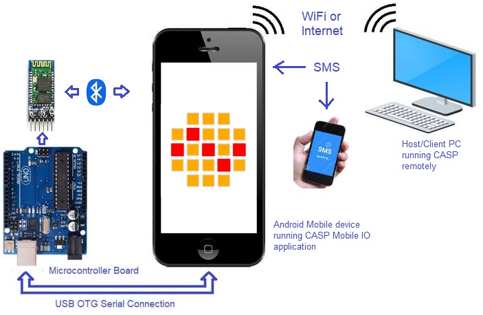
CASP Mobile IO application runs on Android based mobile devices. It converts your old or unused smart phone to an IoT based data acquisition and control hub with minimum external components and wiring. Following are the functionalities of this software
1. Acquires data from internal sensors such as GPS location, accelerometer, gyroscope, magnetic compass, light and temperature sensors.
2. Communicates (as a host) with any CASP supported micro-controller board connected to the mobile device though USB port (OTG cable may be required for old mobiles) or Bluetooth for local data acquisition and control.
3. Communicates with remote host (as a device) through WiFi or Internet (IP4 or IP6) and transfers locally acquired data (from internal sensors and externally connected micro-controller) to the host and receives control commands from the host for local control. Data encryption is supported for host communication.
4. Sends requested data points (sensor data, IP addresses and data collected from external micro-controller) through SMS to the remote SMS sender. Similarly, it receives control commands from SMS for local control.
5. Supports mobile devices with Android 6 (Marshmallow 2015) and above.
Security
This app doesn’t collect or send any personal data. It may ask for permissions to access WiFi/internet, SMS read/write, USB device access, access to Bluetooth connected devices, GPS location access etc. as and when respective features are enabled and used in the app.
Getting Started
1. Grab any unused Android smart phone that supports WiFi, USB OTG and Bluetooth. Temporarily enable ‘Install from unknown sources’ in Android OS if this app is to be installed from sources other than Google Play Store.
2. Download and install this app from our website or any authenticated sources. If downloaded from our website, choose right file based on the architecture as below
- casp_mobile_io_arm7.apk works on almost all mobile phones with ARM7 and later architectures
- casp_mobile_io_arm8.apk for ARM8 and later architectures
- casp_mobile_io_x86.apk specifically for x86 architectures
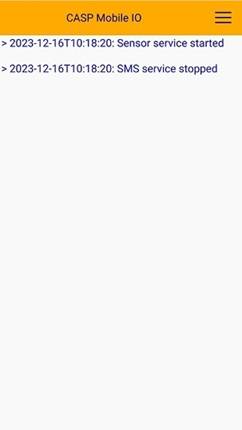
3. Run the app to show below screen
|
|
|
|
Main Window |
Menu Options |
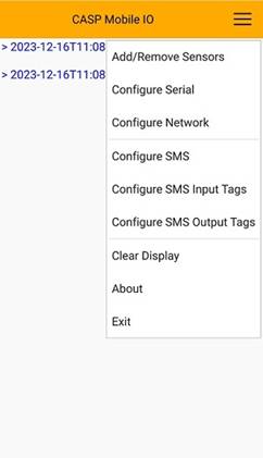
4. App documentation can be viewed by clicking on ‘About’ from the menu option as shown above.
5. Please note that most of the sensors including GPS will work only when the app is in foreground.
Internal Sensor Configuration
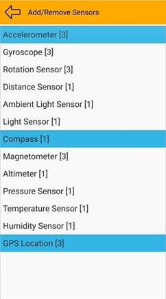
Each internal sensor data point is represented by a 32-bit (4 byte) floating point data type. Sensors such as accelerometer, gyro, gps etc. takes 3 data points, accordingly they require 12 bytes in the data buffer to be transferred to the remote host. For adding/removing individual sensors, select main menu and click ‘Add/Remove Sensors’ menu item. This will open up below window with sensor list that the app supports. Some sensors in the list may not be supported by the hardware for which 0 is shown as the data point value. Number of data points required by each sensor is shown in square brackets against each sensor.
|
|
Configuring Serial Communication Parameters
CASP Mobile IO communicates with external micro-controller (MC) connected via USB OTG or Bluetooth. The external MC shall be programmed with CASP with serial communication block. The input output data sizes (in Bytes) configured in the MC shall match exactly with that configured here. This app can only communicate with one external MC at any given time. Select main menu and click ‘Configure Serial’ menu item. This will open up below window. Select ‘Enable’ to enable USB/ Bluetooth support. Select USB device if MC is connected to the USB port. Baud Rate, Parity, Flow Control options are applicable only for USB connected device.
|
|
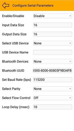
Before using Bluetooth (BT) the MC should be paired with the mobile device. List of paired devices will appear in the ‘Bluetooth Devices’, user may select the BT device where the MC is connected. Default Bluetooth UUID represents BT serial devices, sufficient for most cases.
Configuring Network Communication Parameters
CASP Mobile IO communicates with remote host through network communication protocols such as TCP/UDP over IP4 or IP6. On board WiFi or 3G/4G mobile network can be used for this purpose.
|
|
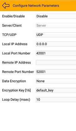
Select Enable to enable network communication. Select UDP/TCP and select suitable IP address. Better to select 0.0.0.0 for IP4 and ‘::’ for IP6. This ensures the device always listens for connections even if underlying IP address changes. The remote host can enquire about the IP address by sending SMS for IP address. This is further discussed in next section. User may leave rest of the options for defaults. Select ‘Data Encryption’ method to enable data encryption. Enter suitable encryption key (maximum 16 characters) as desired.
The data is transferred as a series of bytes. Data from external MC is placed at starting followed by the data from the sensors in the order of their selection. Example with options shown above first 16 bytes are from external USB/Bluetooth device followed by accelerometer (12 bytes), compass (4 bytes) and GPS (12 bytes) data. Total 44 bytes are send from this device to the remote host. Accordingly, remote host receive data size shall be set as 44 bytes. Remote host data send size shall be minimum 16 bytes to match with USB/BT output data size. .
Configuring SMS Parameters
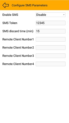
CASP Mobile IO can receive SMS from another mobile device and replies back with requested data. To enable this feature select ‘Enable’ from Enable SMS option (see below figure) and set suitable SMS token (it is like a security key). Set ‘Remote Client Number1 to 4’ (format: +<12-digit phone number>. e.g. +919545812625) to only respond to SMSs from any of these numbers.
|
|
The received SMS shall be in the following format: <sms_token>,<r/i/s/b/0-7>-<start byte index>=<val>, where
<sms_token>: indicates SMS token as configured above.
<r/i/s/b/0-7>: where ‘r’ indicates 32-bit floating point data type, ‘i’ indicates signed 32-bit integer data type, ‘s’ indicates signed 16-bit integer data type, ‘b’ indicates byte data type, 0 to 7 refers to bit indexes in a byte. This field is important as the user may configure the input/output data as one of the data types mentioned above.
‘-’: separator between data type and start byte index fields.
<byte index>: byte index of the input and output port data.
‘=’: if equals symbol is present then it is a write operation else read operation.
<val>: indicates value of write operation. Valid only if ‘=’ is present.
For example: if a SMS is received with text “12345, i-0=15685, r-4=12.5, b-8=135, r-0, s-4, 0-6” without the quotes then the software first checks for the matching token number with that configured. If matched then it converts 15685 into 32 binary integer and outputs at serial output data index 0 to 3. Similarly, it converts 12.5 to 32-bit floating point binary data and outputs at output index 4 to 7, 135 to 1 byte binary value and outputs at output index 8. It then converts binary data received from serial device at index 0 to 3 to 32-bit floating point text, input index 4 and 5 to 16-bit signed integer text, input index 6 first bit (bit-0) to text ‘1’ or ‘0’ and sends back SMS to the master with text format similar to that mentioned above. i.e. r-0=2548.1,s-4=280,0-6=1. User should ensure that byte indexes are not overlapped or repeated among different fields.
|
|
|

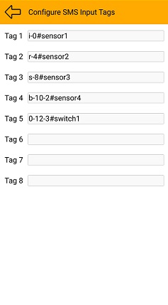
This block also supports user to assign upto 8 human understandable tags against each of the above text for inputs and outputs separately. For example setting ‘sensor1’ for r-0 will enable user to send SMS with text sensor1 instead of r-0. This can be configured from ‘Configure SMS Input/Output Tags’ options as shown above. Please note that the tag length should be as minimum as possible and is case sensitive.
Inbuilt tags can also be specified along with above tags as listed below. Syntax is <token number>,<tag>
- help: sends back text similar to ‘help=tags,itags,otags,ftags’
- tags: lists out inbuilt supported tags as given below
· gps: sends gps co-ordinates. Example: SMS received with text ‘12345,gps’ will send ‘gps=12.2343,76.34343’ as the reply SMS
· gpsurl: sends back gps co-ordinates in a Google Maps URL format.
· acc: sends accelerometer data
· gyro: sends gyroscope data
· mag: sends compass value in degrees
· light: sends light value
· temp: sends temperature value
· ip4: sends detected IP4 address
· ip6: sends detected IP6 address
- itags: sends list of pre-configured input tags in ‘Configure SMS Input Tags’
- otags: sends list of pre-configured output tags in ‘Configure SMS Output Tags’
- ftags: sends the format of io tags i.e. [i/r/s/b/0..7]-[start_index]=[val]