RS485 Communication with CASP
This example project demonstrates how to establish RS485 communication between two target boards and the host (native) PC. We try to acquire analog data from the target boards to the host PC through RS485 communication and plot the data on the host PC. We also try to control the on-board LED present the target boards from the host PC.
Hardware Required
Arduino Uno and Arduino Nano targets are used in this project. However, any supported boards can be used.
USB to RS485 Converter Module
RS485 to TTL Converter Modules
Description
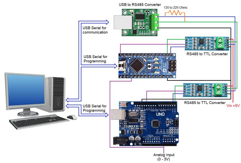
Connect any sensor to the ADC pin A0 of Arduino Uno and Arduino Nano for sensing. We use the on-board LED at pin-13 for controlling. Connect the two boards along with the RS485 converter modules to the host PC as shown in the circuit diagram. A resistor of value between 120 to 220 Ohms shall be connected between RS485 communication wires (A & B). Following are the steps to properly program the Arduino and native targets to achieve above objective.
· Connect Arduino Uno to the host PC via a USB cable.
· Note the serial port number to which the board is connected to the host PC, from the host operating system.
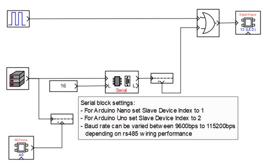
· Run CASP and load the ‘target_model’ project. Ensure that the Slave Device Index parameter of the Serial block is assigned properly as mentioned in the model.
· Open Home->Simulation->Setup Simulation Parameters menu item. Under TargetHW->General tabs set ‘Target Hardware Programmer Port’ parameter to the serial port to which the board is connected.
· Build the model and program the board by clicking on Run button.
· Repeat the above steps to program Arduino Nano board.
· After the two boards are programmed, close the current project and load the ‘native_model’ project.
· With the USB to RS485 module connected to the host PC, click on Home->Simulation->Configure Simulation IO menu item.
· ‘Configure Simulation Hardware’ window will open. Change the serial port marked in the below figure (by double clicking on the item) to the port where USB to RS485 module is connected.

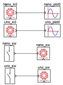
· Click on ‘Connect Device’ button and check the ‘Online Data’ check box. The program should now communicate with the two targets with cycle time around 10msecs. If cycle time is more than this value then configure USB to RS485 module serial port latency settings to the minimum value. Target boards are now available as end points EP0 and EP1 to the native model. Native model can use these end points to connect to respective IOs on the targets.
· Click on ‘Save’ button to save the configuration and close the window.
· Run the model by clicking on the Run button. A simulation panel window should open and communicate with the two boards. A screen shot is shown below.

· From the simulation panel toggle the two switches to control the on-board LEDs of the two targets.
Circuit Diagram
Model
Target Model
Native Model
References
Please go through our video tutorials, tutorial projects and CASP main documentation for getting started with CASP.