WiFi101 Communication with CASP
This example project demonstrates how to establish WiFi communication from host PC to the target boards that supports on-board WiFi101 library. We try to acquire analog data from the target board to the host PC through WiFi and plot the data on the host PC. We also try to control the on-board LED present on the target board from the host PC.
Target
Arduino MKR1000 is used in this project. However, ESP32S, Arduino RP2040 Connect and any board supporting WiFi101 library and supported by CASP can be used.
Description
Connect the circuit as shown below. Connect any sensor to the ADC pin A0 of the target board for sensing. We use the on-board LED at pin-6 for controlling.
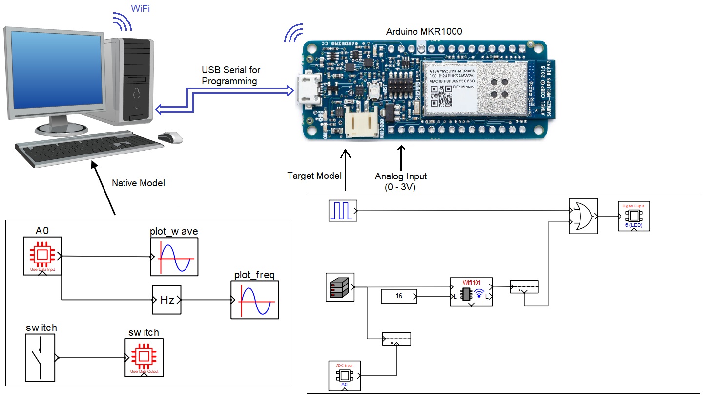
Following are the steps to properly program the target board.
· Connect the target to the host PC via a USB cable.
· Note the serial port number to which the board that is connected to the host PC, from the host operating system.
· Run CASP and load the ‘target_model’ project.
· The WiFi101 block WiFi is set to Station mode. User may need to enter SSID and password of the network to which the device should be connected. The Local IP address parameter shall be configured as assigned by the network DHCP client of the network.
· Open Home->Simulation->Setup Simulation Parameters menu item. Under TargetHW->General tabs set ‘Target Hardware Programmer Port’ parameter to the serial port to which the board is connected.
· Build the model and program the board by clicking on Run button.
Following are the steps to run the native model on the native PC
· Before continuing, the host PC shall be connected to the same network as the device is connected.
· Load the ‘native_model’ project.
· Click on Home->Simulation->Configure Simulation IO menu item.
· ‘Configure Simulation Hardware’ window will open. Under Native Nodes and GPIO Device Nodes, change the IP addresses marked in the below figure (by double clicking on the item) to respective local and device IP addresses.

· Click on ‘Connect Device’ button and check the ‘Online Data’ check box. The program should now communicate with the target with cycle time less than 20msecs. Target board is now available as end point ‘EP0’ to the native model. Native model can use this end point to connect to respective IOs on the target.
· Click on ‘Save’ button to save the configuration and close the window.
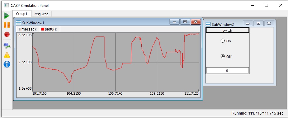
· Run the model by clicking on the Run button. A simulation panel window should open and communicate with the board.
· Screen shot of the output simulation panel running on host PC is shown below.
References
Please go through our video tutorials, tutorial projects and CASP main documentation for getting started with CASP.