ESP32 Camera Configuration Project
Introduction
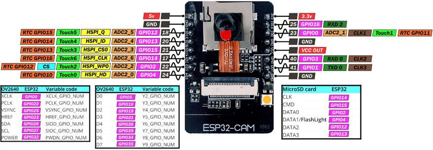
This project demonstrates how to program/configure ESP32 camera module. Typical ESP32 camera module pin diagram is shown below.
Procedure
To properly program the ESP32 camera module following steps are required to be performed.
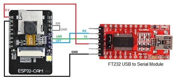
Step 1: Connect ESP32 camera module to a FT232 USB to Serial converter module as shown in below figure. Set the jumper of the FT232 module to 5V and connect it to the host PC via a suitable USB cable.
Step 2: Ensure that CASP board support package (BSP) for ESP32 is properly installed before continuing.
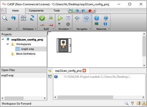
Step 3: Run CASP and open the project. Screen shot after loading the project is shown below
Step 4: Open the ESP32 Camera Configuration block parameters and set the SSID and Password of the WiFi network to which the module will be connected.
Step 5: Click on ‘Setup Simulation’ from the main tool bar and set the serial port to which the module is connected to the host PC as shown below. Also, from the below figure, click on Select button against ‘Target Hardware Build Options’ and select ESP32 Camera from the board options.

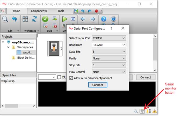
Step 6: Click on serial monitor button at the bottom of the CASP main window and set the serial port to which the module connected as shown in below figure. This will show the serial data coming from the module.
Step 7: Save the project and click on Run button the build and program the module.
Step 8: After programming is done disconnect the wire between the GPIO0 and GND of the ESP32 camera module and press the module Reset button. ESP32 camera module shall now restart and automatically connect to the WiFi network. The status of the module can be monitored in the serial monitor window. IP address of the ESP32 camera model will be displayed in the serial monitor once the module is connected to the WiFi.