Hardware Digital Inputs and Digital Outputs
This example project demonstrates how to model and use hardware digital inputs and digital outputs.
Target
Arduino Uno is used in this project. However, any supported micro-controller board can be used.
Description
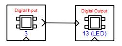
An external switch with suitable bias is connected to digital input pin-3 of the target board. Digital output is taken from pin-13 which is already connected to on-board LED. Logic is modelled to ON the LED when the switch is closed.
Circuit Diagram

Model
References
Please go through our video tutorials, tutorial projects and CASP main documentation for getting started with CASP.