Hardware ADC, PWM and DAC
This example project demonstrates how to model and use an ADC input and PWM/DAC output.
Target Hardware
Arduino Uno for ADC to PWM
Arduino Due for ADC to DAC
However, any supported micro-controller board can be used.
Description
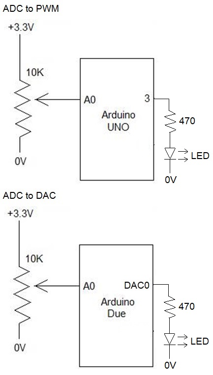
The input voltage at pin A0 is varied by connecting an external variable resistance as shown in the circuit diagram. The PWM output at pin-3 and DAC output at pin-DAC0 are connected to external LED with suitable resistor in series. Logic is modelled to vary the brightness of the LED with respect to the voltage at A0. User needs to manually change the target to switch between Arduino Uno and Arduino Due during modelling.
Circuit Diagram
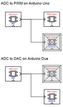
Model
References
Please go through our video tutorials, tutorial projects and CASP main documentation for getting started with CASP.