Using NEO-6M GPS Module with CASP
This example project demonstrates how to interface NEO-6M GPS module on micro-controller targets as well as on the native target using CASP.
Target
Arduino Leonardo is used in this project as the micro-controller target. However, any supported micro-controller board can be used. Please note that Arduino Uno cannot be used if USB serial is enabled.
Description
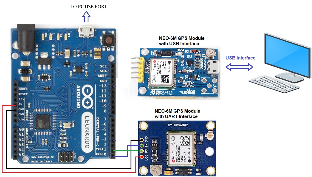
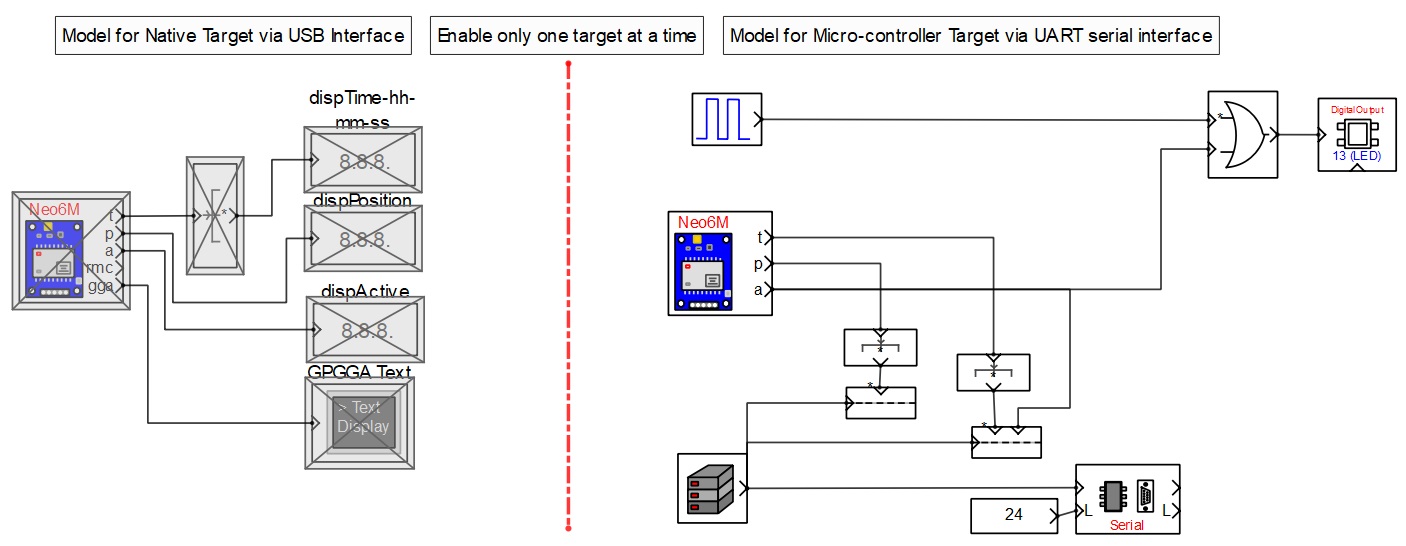
NEO-6M GPS module is connected to the target board as shown in the circuit diagram. If the GPS module supports USB interface it can also be connected to the host PC directly. This example shows both interfaces. Two models (one for micro-controller target and the other for the native target) are developed to communicate with the GPS module and measure some of the parameters such as time in hours, minutes and seconds and location in latitude and longitude. User can also measure other parameters by changing the block configuration.
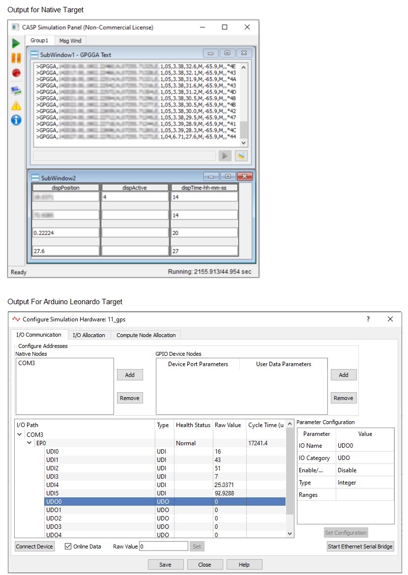
On the micro-controller target the on-board LED blinks steadily if the GPS module position is locked. The measured values are sent to the USB serial port for viewing on the host PC. User can see the measured data from the ‘Configure Simulation Hardware’ interface window by clicking on Simulation->Configure Simulation IO menu item from the CASP main tool bar.
On the native target the text box displays GPGGA formatted text received from the module. Please go through the individual block parameters used in the model along with respective documentation for better understanding.
Circuit Diagram
Model
Output Screen Shots
References
Please go through our video tutorials, tutorial projects and CASP main documentation for getting started with CASP.