Serial Communication with CASP
This example demonstrates how to establish serial communication between the target board and the host (native) PC. We try to acquire analog data from the target board to the host PC through USB serial and plot the data on the host PC. We also try to control the on-board LED present on the target board from the host PC.
Target
Vega Aries v2.0 development board is used as the target in this example. However, any supported board can be used.
Description
Connect any sensor to the ADC pin A0 of the target board for sensing. We use the on-board LED for controlling. First we try communicating with the on-board USB serial communication present on the target from the host PC. Then we try with other two serial interfaces (RX1,TX1 & RX2,TX2) present on the board. Following are the steps to properly program the targets to achieve above objective.
· Connect the target board to the host PC via a USB cable.
· Note the serial port number to which the board is connected to the host PC, from the host operating system.
· Run CASP and load the ‘target_model’ project. From the ‘TargetHw Serial’ block parameters set the ‘Serial Port’ parameter as ‘Serial’.
· Open Home->Simulation->Setup Simulation Parameters menu item. Under TargetHW->General tabs set ‘Target Hardware Programmer Port’ parameter to the serial port to which the board is connected.
· Build the model and program the board by clicking on Run button.
· After the board is programmed, run another instance of CASP on the host PC and load the ‘native_model’ project.
· With the target board connected to the host PC, click on Home->Simulation->Configure Simulation IO menu item.
· ‘Configure Simulation Hardware’ window will open. Change the serial port marked in the below figure (by double clicking on the item) to the port where the target board is connected.

· Click on ‘Connect Device’ button and check the ‘Online Data’ check box. The program should now communicate with the target with cycle time of around 5 msecs. Target board is now available as end point ‘EP0’ to the native model. Native model can use this end point to transfer data with respective IOs on the target.
· Click on ‘Save’ button to save the configuration and close the window.
· Run the model by clicking on the Run button. A simulation panel window should open and communicate with the board. A screen shot is shown below.
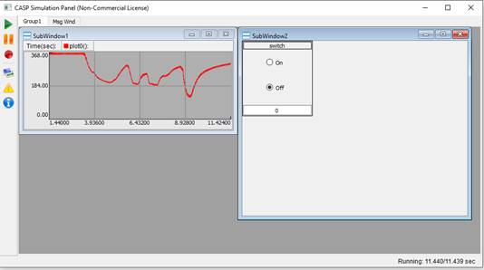
· From the simulation panel toggle the switch to control the on-board LED.
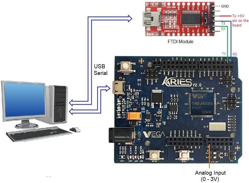
· Connect the target board through a FTDI USB to UART converter module as shown in the circuit diagram.
· In the target board model, set the ‘Serial Port’ parameter of the ‘TargetHw Serial’ block to ‘Serial1’ and repeat the above steps.
Circuit Diagram
Model
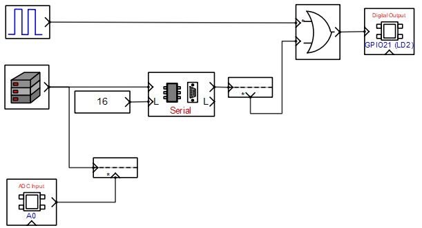
Target Model
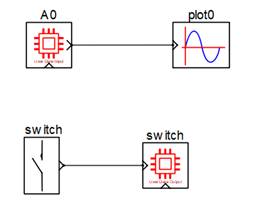
Native Model
References
Please go through our video tutorials, tutorial projects and CASP main documentation for getting started with CASP.