Ethernet Communication with W5500 using CASP
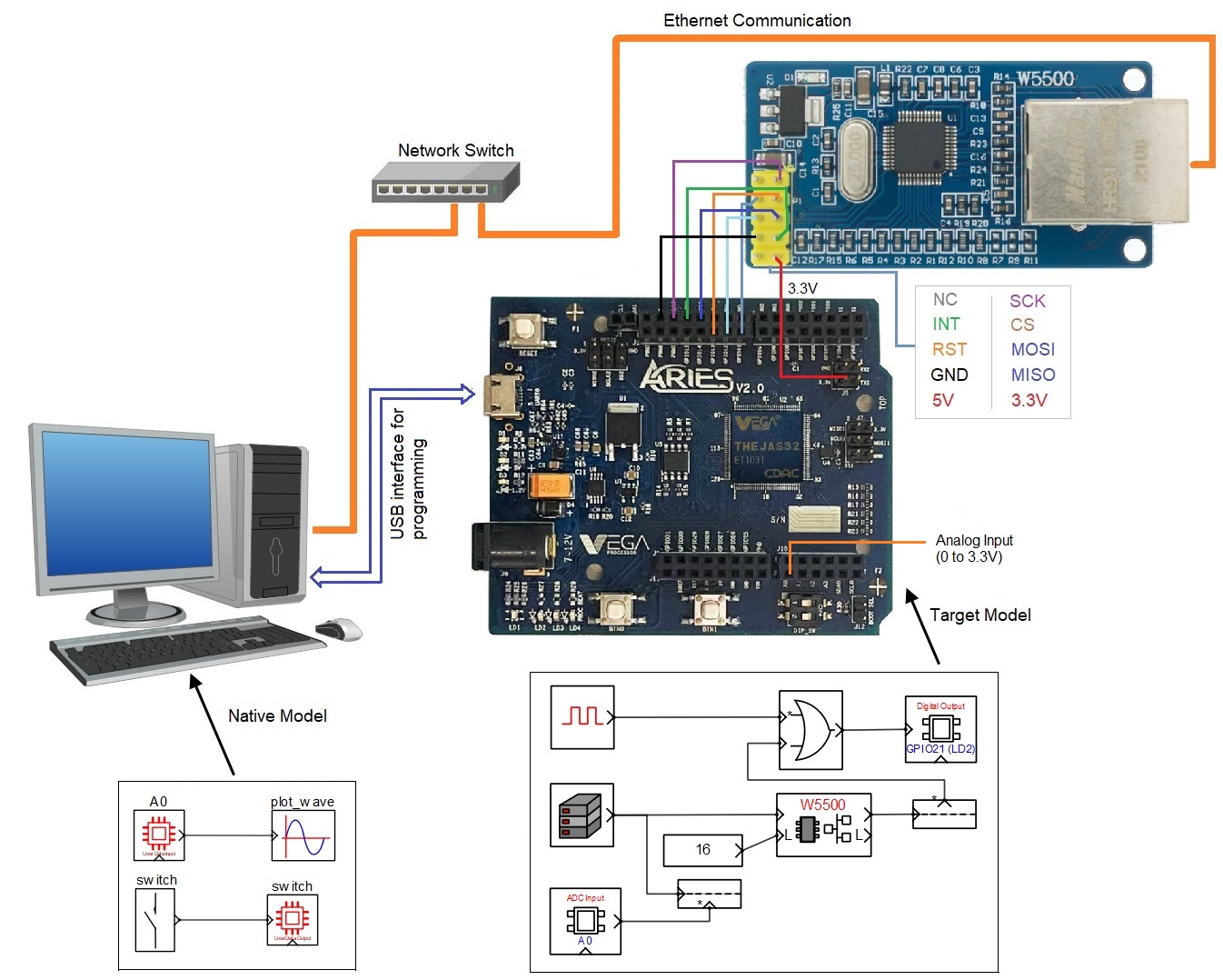
This example demonstrates how to establish Ethernet communication between the target board and the host (native) PC with W5500 Ethernet module. We try to acquire analog periodic signal from the target board to the host PC through Ethernet and plot the signal on the host PC. UDP protocol is used for communicating between the target board and the host PC.
Hardware Required
· Vega Aries v2.0 development board is used for interfacing with W5500. However, any supported boards can be used.
· A suitable signal generator to test the Ethernet latency of complete setup.
Description
Connect the circuit as shown in the circuit diagram.
Following are the steps to properly program the target board.
· Connect the target board to the host PC via a USB cable.
· Note the serial port number to which the board is connected to the host PC, from the host operating system.
· Run CASP and load the ‘target_model’ project.
· Open Home->Simulation->Setup Simulation Parameters menu item. Under TargetHW->General tabs set ‘Target Hardware Programmer Port’ parameter to the serial port to which the board is connected.
· Build the model and program the board by clicking on Run button.
Following are the steps to run the native model on the native PC
· Load the ‘native_model’ project.
· With the target board connected to the host PC, click on Home->Simulation->Configure Simulation IO menu item.
· ‘Configure Simulation Hardware’ window will open. Under Native Nodes and GPIO Device Nodes, change the IP addresses marked in the below figure (by double clicking on the item) to respective local and device IP addresses.
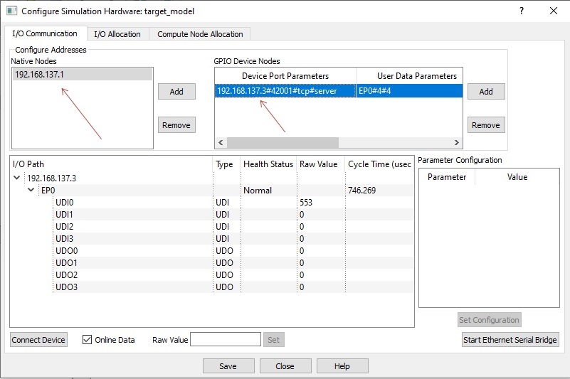
· Click on ‘Connect Device’ button and check the ‘Online Data’ check box. The program should now communicate with the target with cycle time less than 2msecs. Target board is now available as end point ‘EP0’ to the native model. Native model can use this end point to connect to respective IOs on the target.
· Click on ‘Save’ button to save the configuration and close the window.
· Run the model by clicking on the Run button. A simulation panel window should open and communicate with the board.
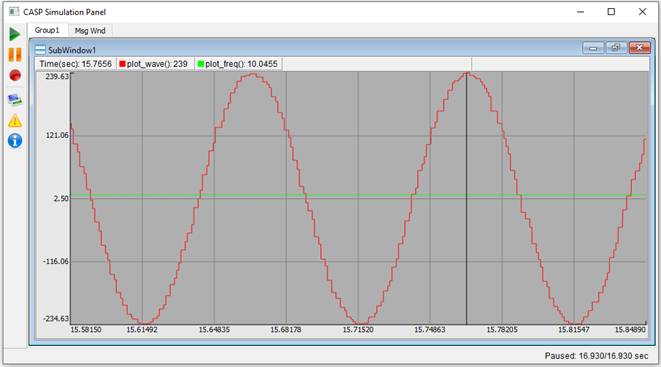
· Screen shot of the output for 10Hz frequency sine wave source connected to the A0 pin.
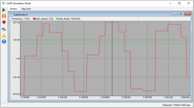
· Screen shot of the output for 100Hz frequency sine wave source connected to the A0 pin.
Circuit Diagram & Models
References
Please go through our video tutorials, tutorial projects and CASP main documentation for getting started with CASP.