Hello World with Vega Aries v2.0 Development Board
This example project demonstrates how to create a simple model
· To blink an on-board LED (LD2)
· To control a servo connected to PWM pin with a sine wave generator
· To control the on-board LED (LD3) and RGB LEDs based on voltage magnitude applied at ADC pin.
· How to use a custom block with user source code to realize user specific logic that cannot be implemented with CASP blocks.
Target
Aries v2.0 development board is used in this project. However, any supported micro-controller board can be used.
Pre-Requisites
CASP has to be installed on the host PC along with board support package files of the Aries v2.0 board.
Circuit Diagram
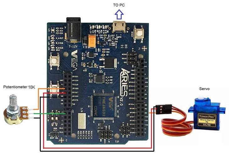
A servo is connected to PWM0 pin and a potentiometer is connected to A0 pin of the board as shown in the below figure. The board itself is connected to the host PC with a suitable USB cable. It is suggested to connect the board to USB2.0 compatible port if the board is not detected when connected to USB3.0 port of the host PC.
Model
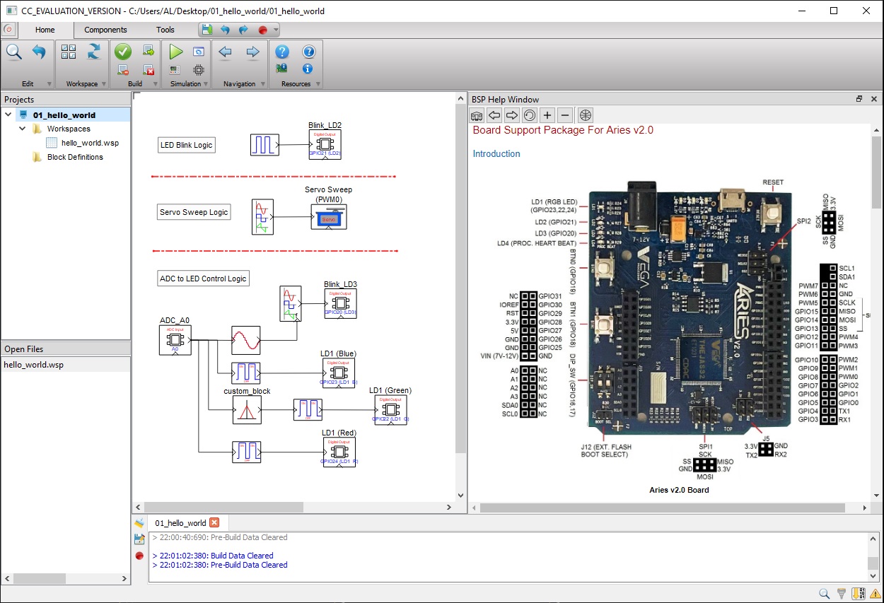
Model to realize the logic is shown in below figure. A custom block (custom block is a user created block consisting of user specific C/C++ code) is also used to vary the brightness of Green LED (of LD1) such that its brightness is maximum at half the applied voltage and decreases linearly when applied voltage deviates from its center value. User can refer to our Tutorial-9 at https://aadhuniklabs.com/casp_res_tutorials and video https://aadhuniklabs.com/casp_res_videos/#custom_block on how to create and use a custom block.
Procedure
1. Connect the board to the host PC.
2. Launch CASP and open the example model.
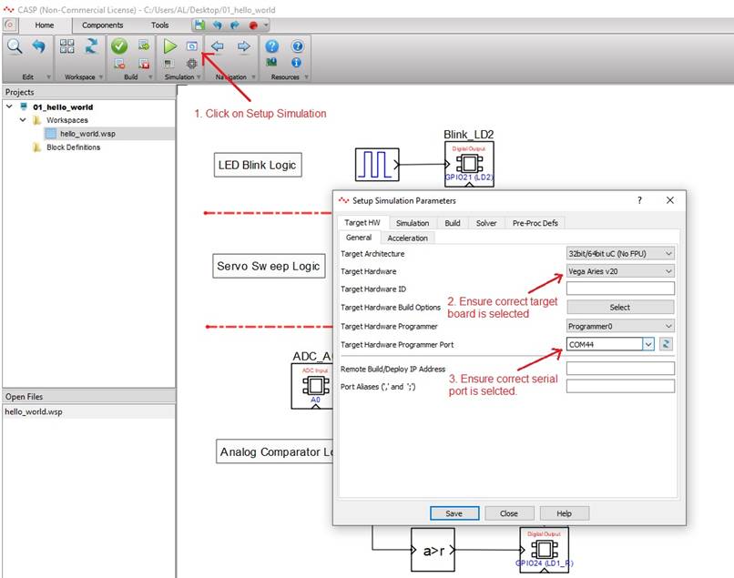
3. Click ‘Setup Simulation’ and set the serial port to which the board is connected. See below figure.
4. Click Run button to build and program the board.
5. Observe the on-board LED (LD2) blinking and the servo rotating smoothly.
6. Vary the potentiometer from 0.1 to 3.3V and observe the changing in color of the on-board RGB LED (LD1) from Blue to Red. Also, observe the increase in blink rate of LED (LD3)
References
Please go through our video tutorials, tutorial projects and CASP main documentation for getting started with CASP.