Servo and Stepper Motor Control
This example project demonstrates how to control a servo and stepper motor using CASP.
Target
Vega Aries v2.0 board is used in this project. However, any supported micro-controller board can be used.
Description
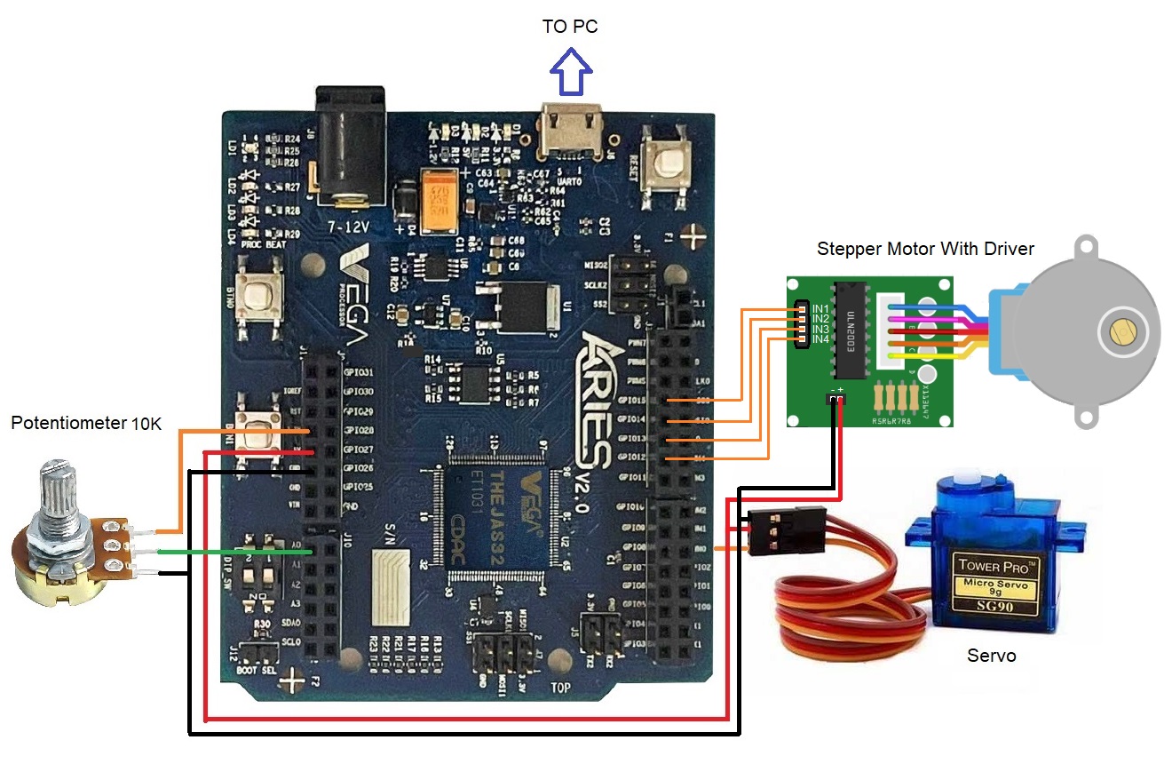
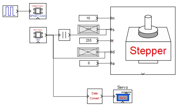
A variable voltage is applied to pin A0 pin of the target board through a variable resistor. A servo is connected to pin PWM0 and stepper motor driver pins are connected to the pins-GPIO12 to GPIO15 of the target board as shown in the circuit diagram. A model is created to control the servo angle and the stepper motor speed & direction by varying the voltage at pin A0. If the voltage is more than half, the stepper motor rotates in one direction else it rotates in opposite direction. Speed can be varied by varying amplitude of the voltage. Similarly, servo angle is varied by varying the input voltage. Please go through the individual block parameters used in the model along with their documentation for better understanding.
Circuit Diagram
Model
References
Please go through our video tutorials, tutorial projects and CASP main documentation for getting started with CASP.