Interfacing with 8x8 Dot Matrix Display
This example project demonstrates how to measure speed of a motor and display on a 4 into 8x8 Dot Matrix Display modules with CASP.
Target
Vega Aries V2.0 is used for this project. However, any supported micro-controller can be used.
Description
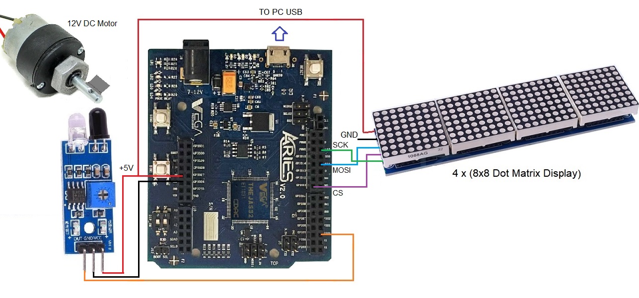
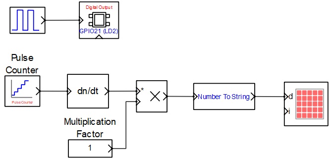
An infra red proximity sensor is connected to GPIO0 of the target board. A 4 into 8x8 dot matrix display is connected to the board via SPI interface as shown in the circuit diagram. A model is developed to measure the number of counts the motor shaft rotates and correspondingly the speed in RPS and display on the dot matrix display. To display the speed in RPM modify the ‘multiplication factor’ block value from 1 to 60. Please note that interrupt is enabled on GPIO0 by default for better timing. However, user may disable the interrupt and enter suitable value in the ‘Debounce Time’ parameter in the ‘pulse counter’ block if the sensor signal is noisy. Please go through the individual block parameters used in the model along with respective documentation for better understanding.
Circuit Diagram
Model
References
Please go through our video tutorials, tutorial projects and CASP main documentation for getting started with CASP.