Interfacing with SD Card module
This example project demonstrates how to read and write to SD card module using CASP. Please go through the SD card block documentation for selecting suitable SD card.
Target
Vega Aries V2.0 board is used in this project. However, any supported micro-controller board can be used.
Description
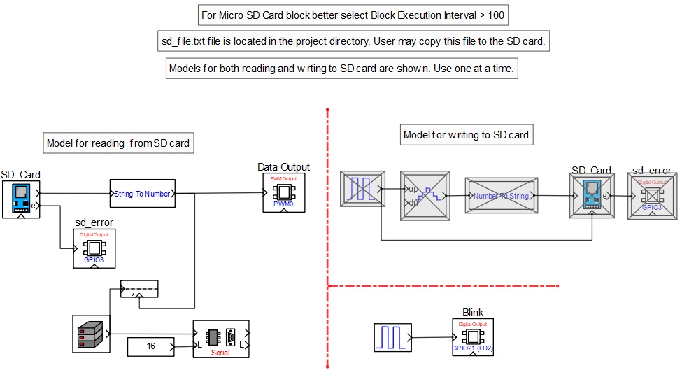
SD card module is connected to the target board as shown in the circuit diagram. Two separate models are developed to read and write integer values to the SD card. User shall enable only one model at a time. User may copy the sd_file.txt file from the project directory to the SD card for this demonstration.
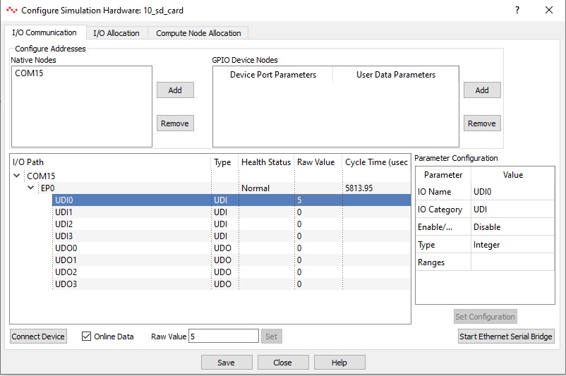
SD card read model reads the numbers from the file, converts to respective integer value and outputs to PWM0 pin to vary its brightness based on the integer value. User can see the integer value read from the SD card from the ‘Configure Simulation Hardware’ interface window by clicking on Simulation->Configure Simulation IO menu item from the CASP main tool bar.
Similarly, the write model counts the number of pulses generated from the pulse generator and writes the count to the SD card file.
GPIO3 pin will be high if the SD card encounters errors during reading and writing. User may enable CASP serial debug feature and check for detailed errors. Please go through the individual block parameters used in the model along with respective documentation for better understanding.
Circuit Diagram

Model
Screen shot of the Configure Simulation Hardware window
References
Please go through our video tutorials, tutorial projects and CASP main documentation for getting started with CASP.