Monitoring and Control of Micro-controller Analog & Digital IOs from Host PC
This example demonstrates how to monitor and control analog & digital inputs and outputs from host PC through WiFi.
Target
Vega Aries v2.0 development board is used as the target in this example. However, any supported board can be used.
ESP8266 WiFi module is used with the micro-controller board to enable wireless connectivity.
Circuit Diagram
Connect any sensor to the ADC pins A0 and A1 of the target board for sensing. On-board LEDs are used for controlling. Two servos may be connected to the PWM2 and PWM3 pins. Connect any DC motor through a suitable driver circuit to PWM0 output of the board.

Description
Following are the steps to properly program the two targets to achieve the above objective.
· Connect the target board to the host PC via a USB cable. The host PC should have a WiFi adapter.
· Note the serial port number to which the board is connected to the host PC, from the host operating system.
· Open Home->Simulation->Setup Simulation Parameters menu item. Under TargetHW->General tabs set ‘Target Hardware Programmer Port’ parameter to the serial port to which the board is connected.
· Build the model and program the board by clicking on Run button.
· The ESP8266 block in the ‘target_model’ is configured as ‘Access Point’ mode with IP address 10.10.0.1. As such, after the board is programmed the on-board LED LD2 should blink after some time indicating that the board is ready to communicate.
· Connect the host PC to the boards WiFi access point. The access point will appear with SSID ‘esp8266_ap’ and password ‘0000000000’.
· After the WiFi connection is established run another instance of CASP on the host PC and load the ‘native_model’ project.
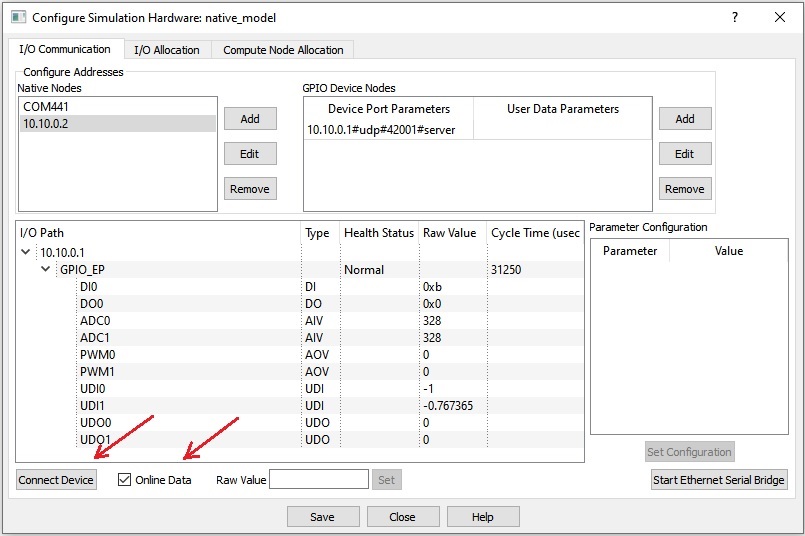
· Click on Home->Simulation->Configure Simulation IO menu item. ‘Configure Simulation Hardware’ window will open. Click on ‘Connect Device’ button to connect to the board as shown in below figure. After the connection is established check the ‘Online Data’ option to start communicating with board with cycle times around 30 msec as shown in below figure. Target board is now available as end point ‘EP0’ to the native model. Native model can use this end point to transfer data with respective IOs on the target.
· Run the model by clicking on the Run button. A simulation panel window should open and communicate with the board. A screen shot of the simulation panel window is shown below.

· From the simulation panel toggle the push button and switch to control the on-board LED.
References
Please go through our video tutorials, tutorial projects and CASP main documentation for getting started with CASP.