Communication between Two IoT Devices using MQTT
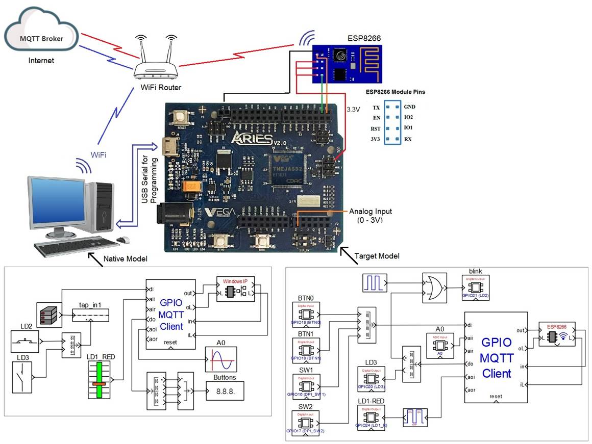
This example demonstrates how to communicate between a remote computer and a micro-controller board located at different geographical locations through IoT MQTT protocol. Both devices shall be connected to the internet. ESP8266 WiFi module is used for connecting the micro-controller board to the internet through a local WiFi router. Analog and digital signals are acquired from the target board and send them to the remote computer where the signals are monitored (plotted and displayed). Some onboard LEDs of the target board are also controlled from the remote computer through the same channel.
In this example the host PC (that is used to program the micro-controller board) is used as the remote computer for monitoring and control. User is encouraged to use any remote computer for monitoring & control and to experience the true potential of the IoT protocol
User has to have access to a MQTT broker for this example to work. This example uses a free online MQTT broker available at the time of testing this example. Same IP address may not work for the user. Some of the free online MQTT brokers available at the time of writing this article are: broker.emqx.io, mqtt.eclipseprojects.io, broker.hivemq.com and public.cloud.shiftr.io. User may try one of these domain names for experimenting.
Target
Vega Aries v2.0 development board is used as the target board in this example. However, any CASP supported boards can be used.
ESP8266 is used to connect the target board to the local network router and to the internet.
Description
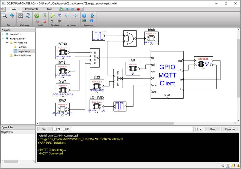
Connect the circuit as shown below. Connect any sensor to the ADC pin A0 of the target board for sensing.
Configuration
· MQTT client ID, publisher and subscriber tokens are already configured in the ‘GPIO MQTT Client’ block on both the device models. User may modify these settings if required.
· The IP address of a MQTT broker can be obtained by pinging its domain name in the Windows command prompt of the host PC as shown in below figure.
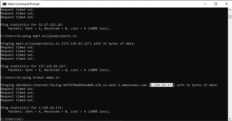
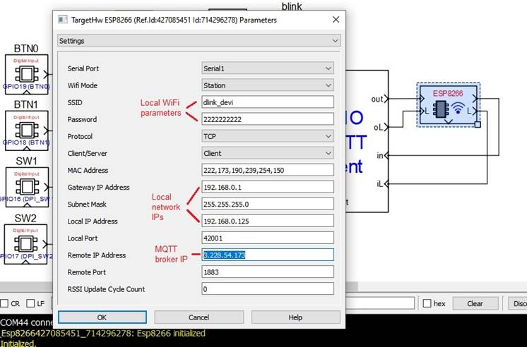
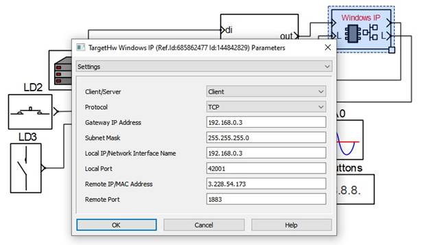
· The IP address thus obtained (shown highlighted in the above figure) can be entered in the configuration parameters of the network blocks of the native and target models. Below figure shows a snap shot of ESP8266 block parameters in the target model. Similar settings shall be configured in the ‘Windows IP’ block of the native model.
Following are the steps to properly program the target board.
· Connect the target to the host PC via a USB cable.
· Note the serial port number to which the board is connected to the host PC, from the host operating system.
· Run CASP and load the ‘target_model’ project.
· Open Home->Simulation->Setup Simulation Parameters menu item. Under TargetHW->General tabs set ‘Target Hardware Programmer Port’ parameter to the serial port to which the board is connected.
· Configure the network parameters of the ‘ESP8266 block’ as shown in above figure. Also, configure MQTT parameters of the ‘GPIO MQTT Client’ model as mentioned in above clauses.
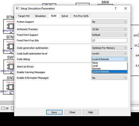
· User may enable CASP debug mode from ‘Setup Simulation’ window if debugging is required as shown in below figure.
· Build the model and program the board by clicking on Run button.
· After programming is completed the board should automatically establish WiFi connection and should connect to the remote MQTT broker.
· A sample screen shot of the debug window with the target board successfully connected to the remote MQTT broker is shown below
Following are the steps to run the native model on the native PC
· After successfully establishing WiFi connection with the target, load the ‘native_model’ project. Configure the ‘Windows IP’ block parameters as shown in below figure
 .
.
· Configure the MQTT parameters of the GPIO MQTT Client model as mentioned above.
· Run the model by clicking on the Run button. A simulation panel window should open and communicate with the MQTT broker. Below message window shows a typical successful MQTT connection

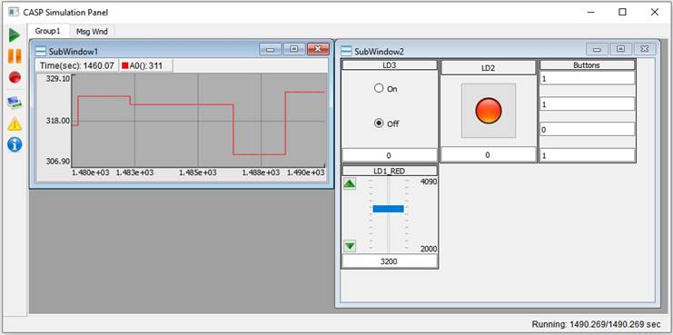
· Below is the screen shot of the simulation window, displaying the data received from the remote target board
References
Please go through our video tutorials, tutorial projects and CASP main documentation for getting started with CASP.