Monitoring Sensor Data of Aries IoT v1.0 board on Host PC
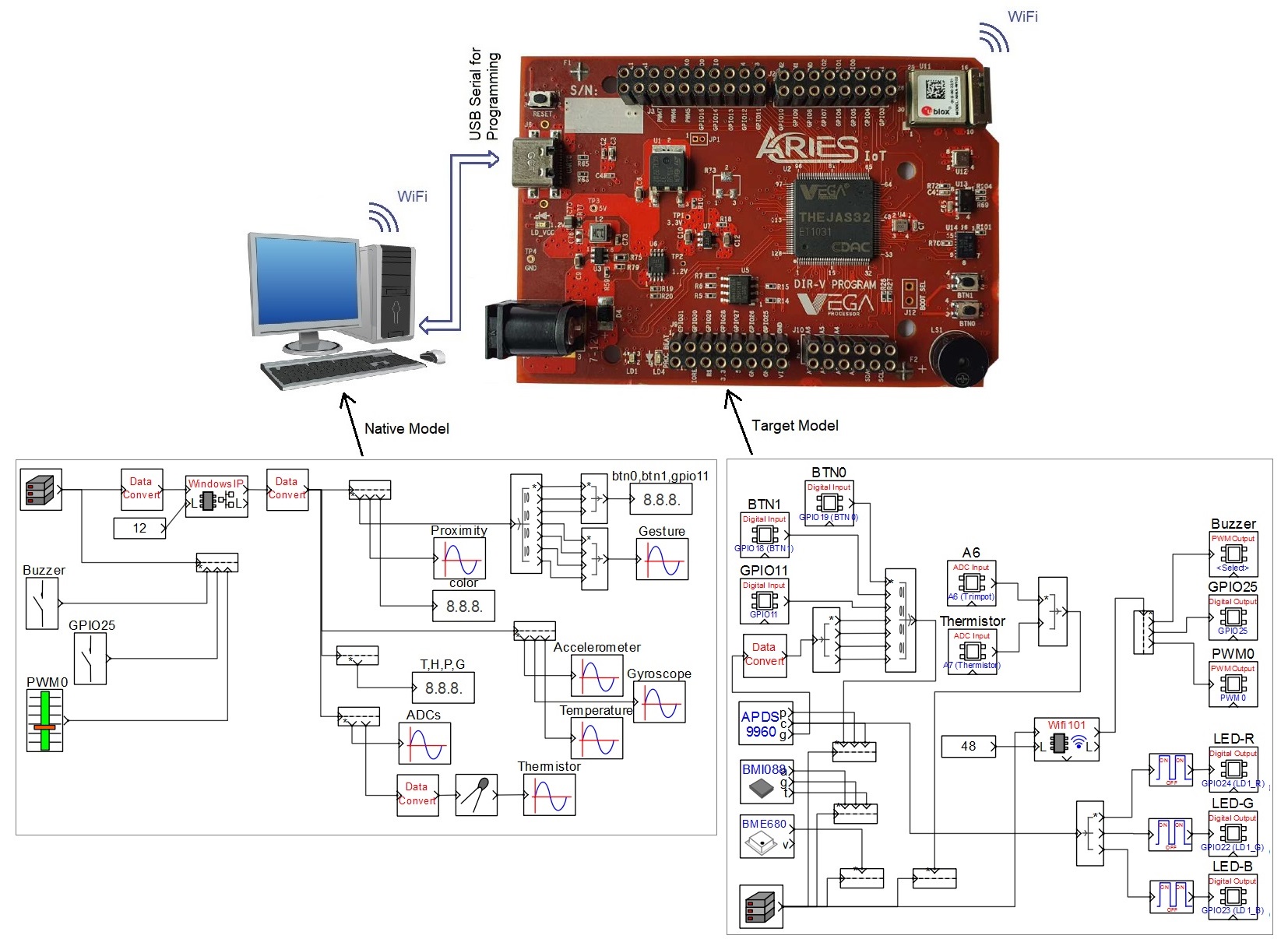
This example demonstrates how to monitor various on-board sensors data from Aries IoT v1.0 board and also control the on-board buzzer and some GPIOs from the host PC through WiFi. Aries ioT board is a versatile micro-controller development board with rich set of peripherals such as
· WiFi module
· Digital Proximity, Ambient Light, RGB and Gesture Sensor
· 6 Axis Digital Accelerometer, Gyroscope Sensor
· Gas, Humidity, Pressure, Temperature Sensor
· Thermistor Potentiometer
· Piezoelectric Buzzer
CASP model that runs on the Aries board consists of blocks corresponding to all the above peripherals. The data is acquired from these peripherals and send via on-board WiFi to the host PC. The model also consists a logic to vary the brightness of the on-board tri-color LED to replicate the color sensed by the on-board color sensor. The model that runs on host PC consists of plots and display blocks to display the data send from the board.
Target
Vega Aries IoT v1.0 development board is used as the target in this example.
Circuit Diagram
Description
Following are the steps to properly program the two targets to achieve the above objective.
· Connect the target board to the host PC via a USB cable. The host PC should have a WiFi adapter.
· The WiFI101 block in the ‘target_model’ is configured as ‘Access Point’ mode with IP address 10.10.0.1. As such, after the board is programmed the on-board tri-color LED should glow with low brightness indicating that the board is ready to communicate.
· Note the serial port number to which the board is connected to the host PC, from the host operating system.
· Open Home->Simulation->Setup Simulation Parameters menu item. Under TargetHW->General tabs set ‘Target Hardware Programmer Port’ parameter to the serial port to which the board is connected.
· Build the model and program the board by clicking on Run button.
· Connect the host PC to the boards WiFi access point. The access point will appear with SSID ‘aries_iot’ and password ‘0000000000’.
· After the WiFi connection is established run another instance of CASP on the host PC and load the ‘native_model’ project.
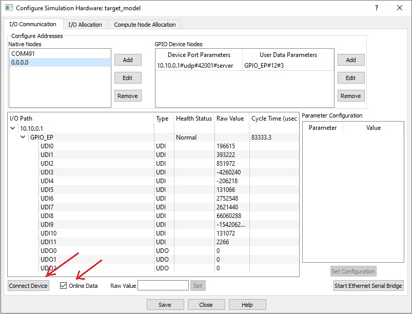
· Click on Home->Simulation->Configure Simulation IO menu item. ‘Configure Simulation Hardware’ window will open. Click on ‘Connect Device’ button to connect to the board as shown in below figure. After the connection is established check the ‘Online Data’ option to start communicating with board with cycle times around 80 msec as shown in below figure.
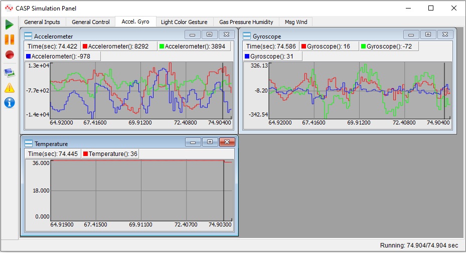
· Run the model by clicking on the Run button. A simulation panel window should open and communicate with the board. A screen shot of the simulation panel window is shown below.
· From the simulation panel toggle the switch to control the on-board buzzer and other GPIOs.
Pre-Build Binary Files and CASP Stand-alone Simulation Panel
To run/simulate the above models without installing CASP, following procedure may be followed.
· Pre-build binaries (simcode.bin and simcode.elf) of the target model are provided in ‘target_model/build/bin_stdl’ directory. Aries IoT board may be programmed directly with these files using suitable programmer provided by the board vendor.
· To communicate with the board from a computer/laptop having WiFi adapter, CASP Stand-alone Simulation Panel program is required to be downloaded to the computer from our website’s downloads page. After downloading, connect the computer’s WiFi to the board’s access point mentioned in the ‘Description’ section above. Extract the downloaded file contents and run the SimPanelLauncher.exe from the ‘bin’ directory. If the program doesn’t start install Microsoft VC++ 2015 runtime libraries provided in the ‘vcredist’ directory and try again. Once the program was launched press the ‘Browse’ button and select ‘native_model/native_model.prj’ project. After selecting the project press the “Launch’ button to launch the simulation panel program. The simulation panel program should run and start communicating with the board through WiFi. The output of the simulation panel window should look similar to the screen shot shown above.
References
Please go through our video tutorials, tutorial projects and CASP main documentation for getting started with CASP.