CASP Tutorial-101 Project
This tutorial demonstrates how to execute model on target hardware.
Pre-Requisites
· Tutorial-1 should be completed.
Hardware Required
· Arduino Uno development board with USB cable.
· Suitable connecting wires
Model
· Arduino Uno development board is used as target hardware.
· Sinusoidal signal generator block output is rooted through PWM port to vary intensity of connected LED.
Hardware Circuit
· Connect pin 3 (PWM pin) and pin 13 (LED pin) of Arduino Uno board.
Step 1: Create New Project
· Follow steps mentioned in Tutorial-1.
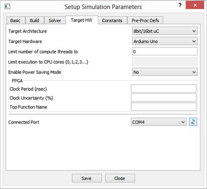
Step 2: Select Target Hardware
· Select target hardware as shown below.
· Select relevant COM port in ‘Connected Port’ field where Arduino Uno board is connected. This port is used to program the board.
Step 3: Creating Model
· Create a model as shown in below figure. Leave signal generator parameters to default.
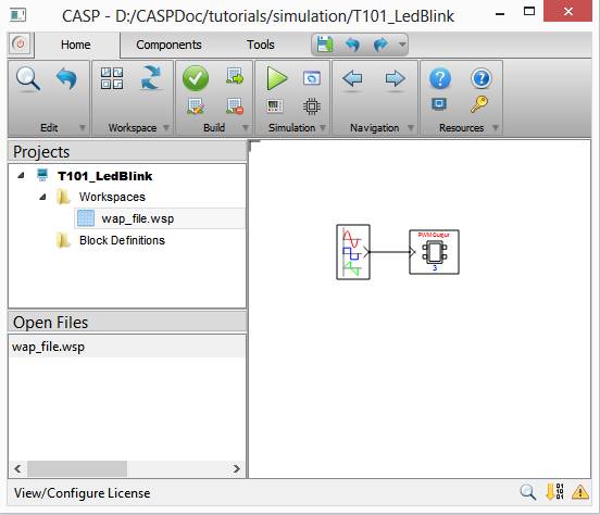
· Configure TargetHw IO block as shown below. Input Range From(To) values indicated in below figure should match with output amplitude range of signal generator.

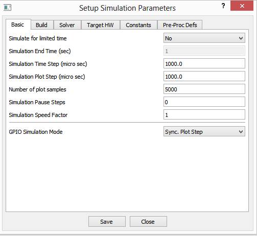
Step 4: Setup Simulation Parameters
· Setup simulation parameters as shown below
Step 5: Build Model and Program Hardware
· Press Build/Run button from Home->Simulation menu item. CASP builds and compiles the model and generates a binary file. The binary file is then programmed to target hardware on selected port Step-2.
· LED brightness can be seen varying smoothly with frequency of 1Hz.