CASP Tutorial-102 Project
This tutorial is an extension of Tutorial-101 LED and additionally demonstrates how to do synchronous communication between model running on target hardware and model running on native hardware.
Pre-Requisites
· Tutorial-2, Tutorial-5 and Tutorial-101 should be completed.
Hardware Required
· Arduino Uno development board with USB cable.
· Suitable connecting wires
Model
· Arduino Uno development board is used as target hardware.
· Sinusoidal signal generator block output is rooted through PWM port to vary intensity of connected LED.
· The frequency of LED is controlled from PC via serial communication between PC and Arduino Uno board.
· Also, the waveform generated in target hardware is send to PC for plotting via the same serial communication link.
· To achieve above purposes two models are created on same workspace. One model will run on target hardware (i.e Arduino Uno Board) for LED blinking and second model will run on native hardware (PC) to control frequency of LED blinking on target hardware and to display the captured waveform from target hardware.
Hardware Circuit
· Connect pin 3 (PWM pin) and pin 13 (LED pin) of Arduino Uno board.
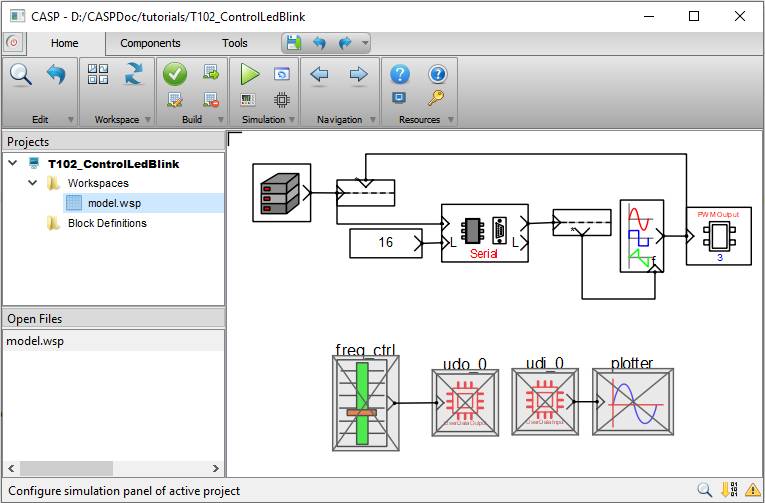
Step 1: Create Target Hardware Model
· Follow steps mentioned in Tutorial-101 to model the below figure. Disable blocks related to native hardware.
· ‘TargetHw Serial’ block is used to establish communication between target hardware and PC. Data Tap-In and Tap-Out blocks are used to insert and extract required data to and from serial block respectively. Communication data length is 16 byte.
· First 4 bytes of serial block receive channel are used to represent 32 bit floating point value for LED frequency control.
· First 4 bytes of serial block send channel are used to represent 32 bit floating point value for waveform generated by signal generator.
· Rest of 12 bytes are unused.
· Data source block is used to generate byte stream of 16 bytes to sending data to PC.
· All blocks shall be accordingly configured.
· Subsequently build and program the hardware.
Step 2: Create Native Hardware Model
· First configure Simulation IO as shown below. Select relevant COM port where Arduino board is connected.
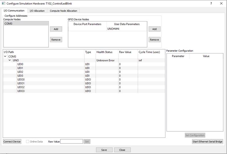
· Follow steps mentioned in Tutorial-2 & 5 to model the below figure. Disable blocks related to target hardware. Set simulation time step as 1000 and plot step as 10000.
.
· Map GPIO block connected to slider block to UDO0 endpoint
· Map GPIO block connected to plotter block to UDI0 endpoint
Step 3: Build and Run Model
· Press Build/Run button from Home->Simulation menu item. CASP builds and compiles the model and opens separate simulation panel window. In the simulation panel window press ‘Run Simulation’ button to run simulation.
· During simulation, try to change slider value to vary frequency of LED blinking
· Waveform captured from target hardware is shown in plotter
 .
.