CASP Tutorial-10 Project
This tutorial demonstrates how to use existing Verilog code using user custom block. For demo purpose ‘Verilog Adder Demo’ block from /blocks/UserBlocks directory is used. The Verilog file is located in VerilogAdderDemo/bin/add.v file. Verilog code in this file performs a simple arithmetic add operation. During build process the code in this file is converted to corresponding C file by verilog to C converter. The converted files are located in VerilogAdderDemo /bin/converted directory.
Pre-Requisites
· Tutorial-2 should be completed.
Model.
· In general user creates a wrapper block with suitable C++ code to interface with C version of Verilog code converted by Verilog to C converter.
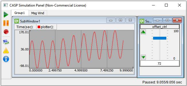
· A sinusoidal signal generator is used along with an offset signal source. Both signals are added in Verilog Demo block and result is displayed on plotter.
Step 1: Create New Project
· Follow steps mentioned in Tutorial-2.
Step 2: Select Target Hardware
· Follow steps mentioned in Tutorial-2.
· Set Target Hardware to Desktop_MinGW_Verilog.
Step 3: Creating Model
· Create a model as shown in below figure.

· Give names to slider and time plotter blocks as shown in above figure.
· Configure signal generator and slider blocks suitably.
· Configure simulation panel and map slider and plotter blocks to simulation panel sub-windows as explained in Tutorial-2.
Step 4: Setup Simulation Parameters
· Follow steps mentioned in Tutorial-2.
Step 5:Run Simulation
· Press Build/Run button from Home->Simulation menu item. During build process CASP first coverts the verilog code C code. The converted C code is compiled with other C/C++ sources generated from model. After successful build the model is executed in separate simulation panel window. In the simulation panel window press ‘Run Simulation’ button to run simulation.
· The output of simulation is shown below.