CASP Tutorial-12 Project
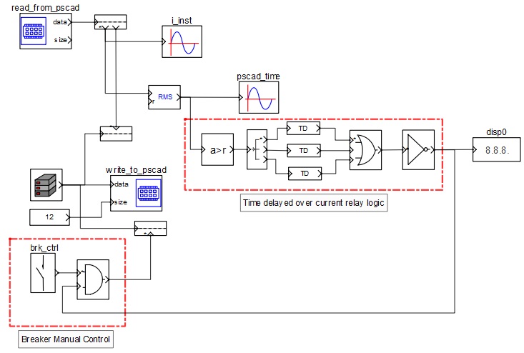
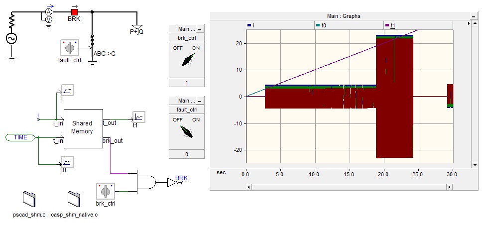
This tutorial project demonstrates how to exchange data between CASP and PSCAD through operating system’s shared memory. A simple electrical network is created in PSCAD with a 3 phase voltage source, a breaker and a PQ load. A fault block is also introduced to simulate a fault. A shared memory custom component is created and added to the model to communicate with CASP. The measured 3 phase currents are connected to the shared memory block along with simulation time. In each simulation time step the block passes these values to CASP through shared memory.
CASP processes the 3 phase currents and time values. It simulates an over current relay logic and generates a command to open the breaker in PSCAD model. The generated command is exchanged back to PSCAD through shared memory.
Pre-Requisites
· Tutorial-2 should be completed.
· User should have a basic knowledge about PSCAD.
CASP Model
PSCAD Model
Step 1: Open CASP project in the folder and start simulation.
Step 2: Open PSCAD project and start simulation. Adjust the simulation time step so that the simulation runs approximately in real time.
Step 3: After PSCAD simulation is started, it exchanges data with CASP automatically. The breaker close command is send from CASP and current starts flowing in the simulated electrical network in PSCAD.
Step 4: User may now simulate fault condition by changing the 'fault_ctrl' switch position to ON state. Observe the increase in current magnitude as and when the switch position is changed to ON state.
Step 5: The increase in current magnitude is sensed by the over current relay logic in CASP. It then generates breaker open command after some time delay and passes on this command to PSCAD to open the breaker.