CASP Tutorial-3 Project
This tutorial demonstrates the following
· How to use physical blocks.
· How to change value of non-linear physical element during run time.
Pre-Requisites
· Tutorial-2 should be completed.
Model
· Electrical RLC series circuit is modelled with sinusoidal AC source of frequency 1Hz.
· R & C values are fixed at 1 Ohm and 10000uF respectively.
· L value is varied between 1000mH and 5000mH during run time to achieve series resonance at 2530mH.
Step 1: Create New Project
· Follow steps mentioned in Tutorial-2.
Step 2: Select Target Hardware
· Follow steps mentioned in Tutorial-2.
Step 3: Creating Model
· Create a model as shown in below figure.
· Give names to current sensor, slider, and time plotter blocks as shown in below figure.
· Set slider value range from 1000 to 5000 with step size of 50. Set initial condition of slider to 1000 as explained in Tutorial-2.
· Configure simulation panel and map slider and plotter blocks to simulation panel sub-windows as explained in Tutorial-2.

Step 4: Setup Simulation Parameters
· Follow steps mentioned in Tutorial-2.
Step 5: Run Simulation
· Press Build/Run button from Home->Simulation menu item. CASP builds and compiles the model and opens separate simulation panel window. In the simulation panel window press ‘Run Simulation’ button to run simulation.
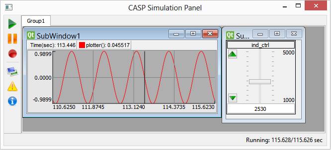
· After initial transient time of 15sec slowly vary the slider value and notice the changes in current. At slider value of about 2530, RLC circuit current value reaches maximum of about 1A indicating resonance condition.
· The output of simulation is shown below.