CASP Tutorial-5 Project
This tutorial demonstrates how to interface with pre-configured external hardware using GPIO block.
Pre-Requisites
· Tutorial-2 should be completed.
Hardware Required
· Arduino Uno development board with USB cable.
· Light Depending Resistor (LDR) with series resistance of 10K Ohm
· Light Emitting Diode (LED) with series resistance of 470 Ohm
· Suitable connecting wires
Model
· Real time voltage data of LDR connected to ADC input of Arduino Uno board is scanned and used in simulation model via GPIO block.
· The scanned data is suitably scaled and send back to Arduino Uno board to vary brightness of LED via PWM output.
Step 1: Import Development Board EPIO model
· Program Arduino Uno board with Atmega328P_Serial.hex file available in /support/mcu_binaries folder using third party programming tools available on internet.
· Import and Save the EPIO model as explained in CASP Documentation -> Project Simulation & Execution -> Simulation IO. Use relevant COM port number where the board is connected.
Step 2: Hardware Circuit
· Build circuit as shown in figure below
Step 3: Create New Project
· Follow steps explained in Tutorial-2.
· Set target hardware as explained in Tutorial-2.
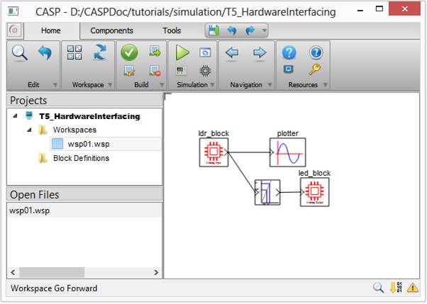
Step 4: Creating Model
· Create a model as shown below.
· Use GPIO blocks (ldr_block and led_block) for interfacing with hardware EPIOs.
· Use Mapping Function block between ldr_block and led_block.
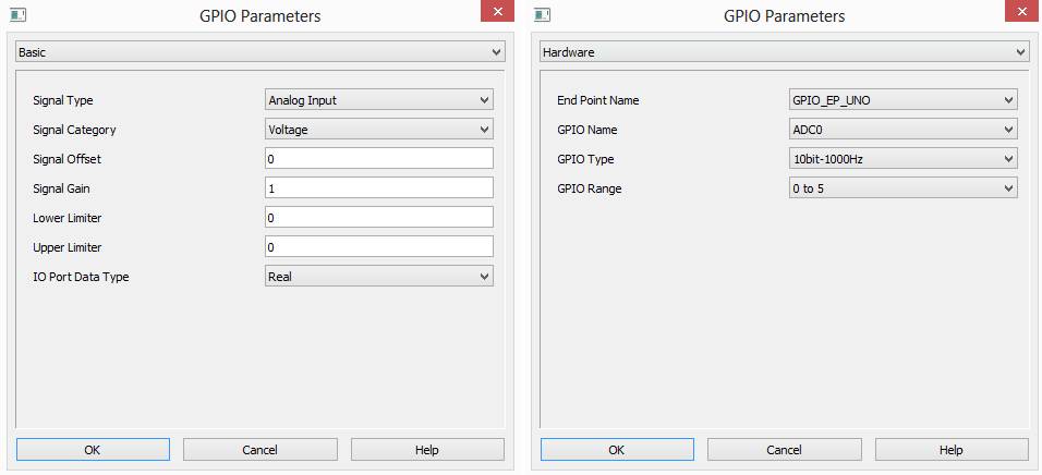
· Configure ldr_block as shown below
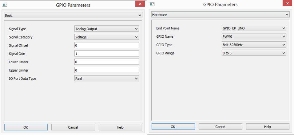
· Configure led_block as shown below
· Configure mapping function block to vary the LED brightness based on amount of light received by LDR. Some trial and error is required here. Typical values are shown below

· Configure simulation panel and map plotter block to simulation panel sub-windows as explained in Tutorial-2.
Step 5: Setup Simulation Parameters
· Follow steps mentioned in Tutorial-2. Modify Basic parameters as shown below

Step 6: Run Simulation
· Press Build/Run button from Home->Simulation menu item. CASP builds and compiles the model and opens separate simulation panel window. In the simulation panel window press ‘Run Simulation’ button to run simulation.
· During simulation run time observe that brightness of LED varies with amount of light falling on LDR.