CASP Tutorial-8 Project
This tutorial project demonstrates how to interface CASP native application running on PC with any external hardware board programmed with 3rd party tools. For the sake of demonstration we have chosen Arduino Uno board programmed with Arduino IDE. User may program the board with his own source code based on his logic requirement. However, for communicating with CASP native application CASP UDIO packet format code indicated in servo_dist_sensor.ino shall be added additionally.
Pre-Requisites
· Tutorial-5 should be completed.
Hardware Required
· Arduino Uno development board with USB cable.
· Ultrasonic distance sensor (HC-SR04 or equivalent) mounted on micro servo.
· Suitable connecting wires
Model
· The Arduino code in servo_dist_sensor.ino receives data from CASP native application through USB serial. The received data is used to control micro servo angle. An ultrasonic distance sensor is mounted on this micro servo and measures the distance of nearby objects. The measured data is send back to CASP native application for further processing.
· CASP native application has suitable model to send the servo angle and receive the distance of nearby objects corresponding to the angle via USB serial link. This angle and distance combination is plotted to create a polar plot.
Step 1: Program Target Hardware Board
· Open Arduino IDE and load servo_dist_sensor.ino sketch from the project directory.
· Compile the sketch for Arduino Uno board and program the sketch to Arduino Uno connected to the PC.
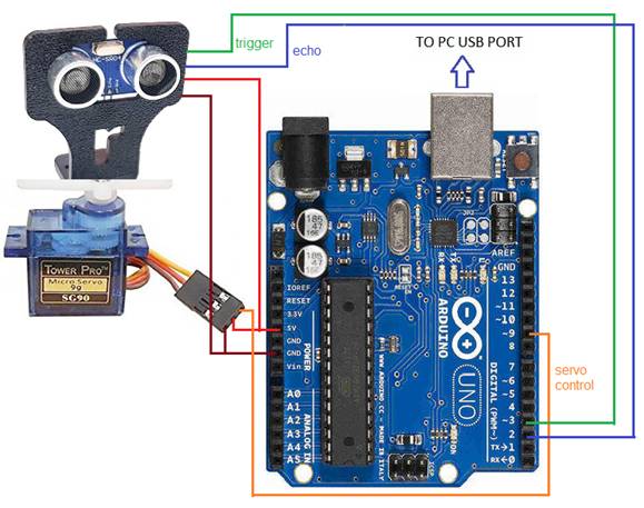
Step 2: Hardware Circuit
· Build circuit as shown in figure below
Step 3: Create New Project
· Create a new project.
· Set target hardware as native with time step of 1000us, plot step multiple as 1 with non-real time simulation.
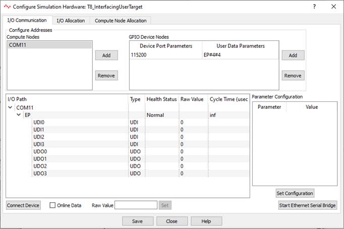
Step 4: Create Native Hardware Model
· First, configure Simulation IO as shown below. Enter COM port where Arduino board is connected. Enter Device Port Parameters such as baud rate equal to 115200 and User Data Parameters as EP#4#4. Where EP stands for end point (any name can be given with maximum characters as 8. First 4 indicate 4 x 4 byte (total 16 byte) data to be received and next 4 indicate 4 x 4 byte (total 16 byte) data to be send to target hardware board.
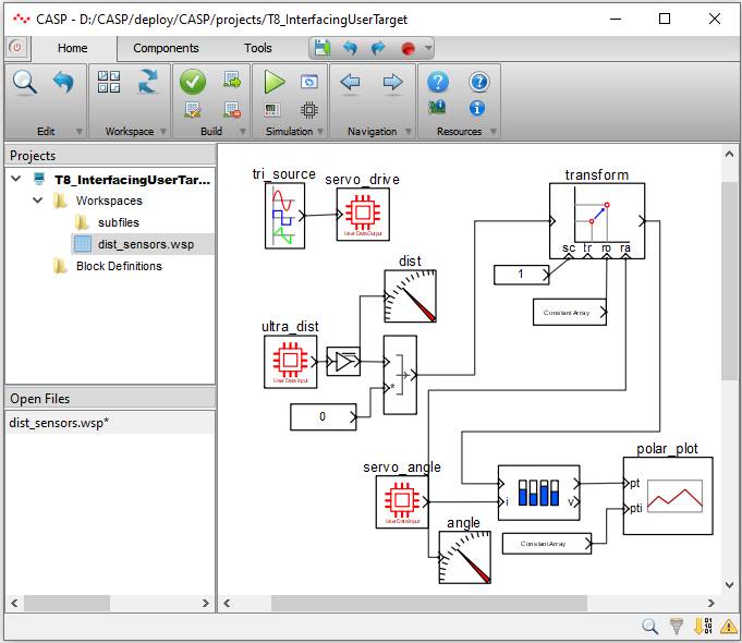
Step 5: Creating Model
· Create a new workspace file. Open the created workspace file and create a model as shown below.
· Blocks tri_source and servo_drive form the triangular wave signal source that drives the servo connected to Arduino Board.
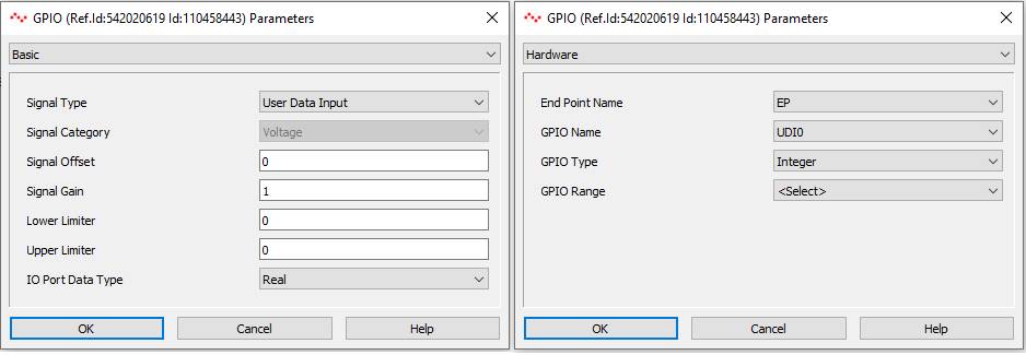
· Ultrasonic distance measurement is received by ultra_dist block and servo angle corresponding to distance measured is received by servo_angle block.
· The received signals are suitably modified and given to polar_plot block for display. User can understand to model by referring to individual block documentation.
· Configuration of servo_drive block is as under.

· Configuration of ultra_dist block is as under.
· Configuration of servo_angle block is as under

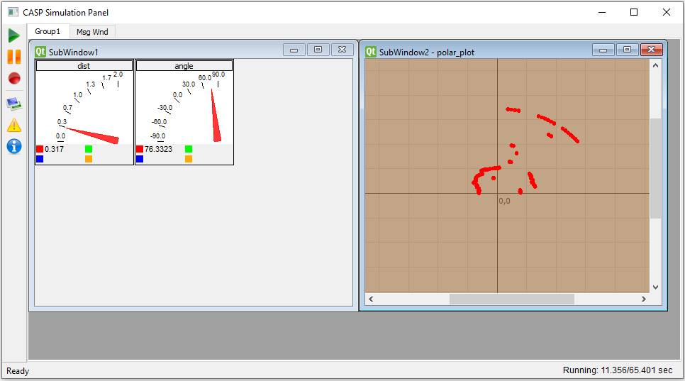
Step 6: Run Simulation
· Press Build/Run button from Home->Simulation menu item. CASP builds and compiles the model and opens separate simulation panel window. In the simulation panel window press ‘Run Simulation’ button to run simulation. The resultant simulation panel is shown below