

CASP User Data Input Output (UDIO) is a light weight communication protocol used to transfer data between the target (such as a micro-controller board or an SBC) and the host computer. CASP UDIO is a customized version of CASP GPIO protocol discussed in previous section. However, unlike CASP GPIO protocol, CASP UDIO transfers user data (such as bytes, integers and floats) instead of GPIO data. Data length should be in multiples of 4 and data is transferred as a contiguous sequence of 4 byte integers or floats irrespective of the underlying data format. The underlying data format can be of any anything that is understandable between sender and receiver.
All CASP communication blocks support this protocol. By tweaking the model suitably, this protocol can even be used to transfer GPIO data.
To use this protocol
Step 1: The target has to be first programmed with suitable CASP model consisting of
§ User logic along with some identified data points that user wants exchange to host through UDIO.
§ Data source block to create array of bytes to transfer to host.
§ Data Tap In and Data Tap Out blocks to insert and extract UDIO data.
§ Communication blocks such as Serial, WiFi, Ethernet blocks to exchange the data to host.
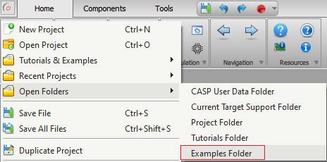
The ‘support/examples/casp_udio_examples’ folder contains UDIO examples for various targets. Documentation for each of these example files is made available at respective example project directory. User can access the ‘examples’ by selecting the ‘Examples Folder’ menu item from CASP main menu as shown below.
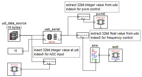
A sample CASP model screen shot for Arduino Uno board from ‘casp_udio_examples/udio_led_control_arduino_uno/control_led_udio_target_uno’ example is shown below. Please refer to the project documentation for further details.
Step 2: Similarly, the host has to be programmed with suitable CASP model that exchanges UDIO data with the target. The host also consists of similar blocks that of the target model. Typical host logic consists of..
§ User logic along with some identified data points that user wants exchange with the target through UDIO.
§ Data source block to create array of bytes to transfer to host.
§ Data Tap In and Data Tap Out blocks to insert and extract UDIO data.
§ Communication blocks such as Serial, WiFi, Ethernet blocks to transfer the data to host.
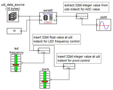
A sample CASP model screen shot for the host model to exchange UDIO data with Arduino Uno target in Step1 is available at ‘casp_udio_examples/udio_led_control_arduino_uno/control_led_udio_native_uno’ example is shown below. Please refer to the project documentation for further details. Unlike CASP GPIO, user can directly run the below model without configuring GPIO from ‘Configure Simulation IO’ window.
Step 3: User can also exchange UDIO data with the target from host computer using Python. This is further elaborated in this section.