

CASP General Purpose Input Output (GPIO) is a light weight communication protocol used to transfer data between the target (such as a micro-controller board or an SBC) consisting of GPIO pins (such as digital input, digital output, ADC, PWM and DAC pins) and the host computer. It allows GPIO pins of the target board directly accessible to the host. With CASP GPIO protocol, user can access the target pins as if they are part of the host computer.
To use this protocol
Step 1: The target has to be first programmed with suitable CASP model consisting of
§ CASP GPIO block connected to the GPIO pins (such as DI, DO, ADC, PWM, DAC etc.) that user wants to expose to the host.
§ Communication blocks such as serial or Ethernet blocks to transfer this data to the host.
§ And any other special logic blocks that user needs to implement (such as servo blocks etc).
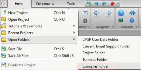
The ‘support/examples/casp_gpio_examples’ folder contains extensive GPIO examples for various targets. Each example folder also contain ready to use binary file in the ‘bin’ sub-folder. User had to just programme the target with this binary file (.bin or .hex) to enable CASP GPIO protocol on that target board. To program the board, CASP programmer interface is available from ‘Tools > Programmer’ menu item of CASP main window. Documentation for each of these example files is made available at respective example project directory. User can access the ‘examples’ by selecting the ‘Examples Folder’ menu item from CASP main menu as shown below.
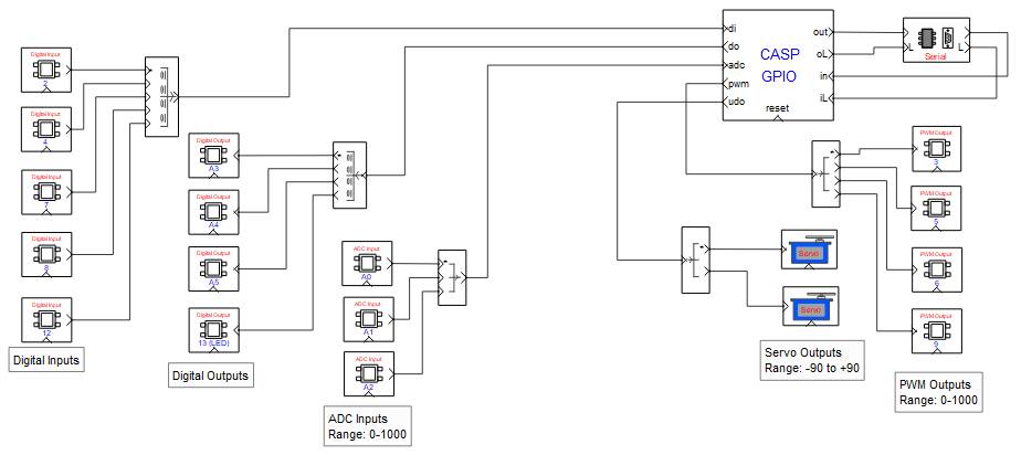
A sample CASP model screen shot for Arduino Uno board from ‘casp_gpio_examples/arduino_boards/casp_gpio_uno_nano_leonardo_serial’ example is shown below. Please refer to the project documentation for further details.
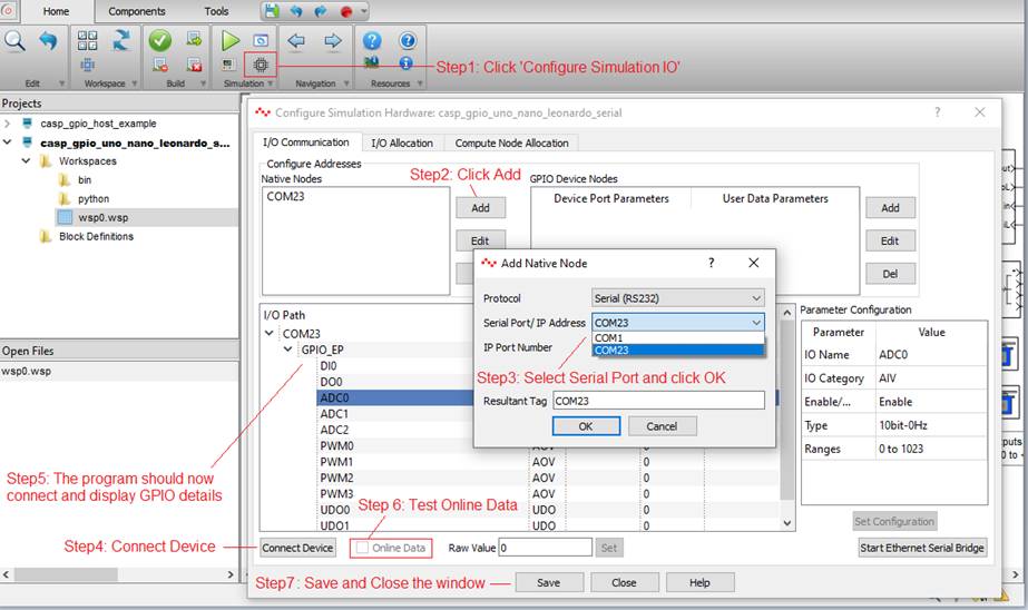
Step 2: Secondly, the host has to connect to the target and configured to access these pins. Please follow the steps shown in below figure to connect to the device: Some old Arduino Uno boards may fail to connect, in such cases try disabling the DTR setting of the serial port in ‘GPIO Device Nodes settings’ of the ‘Configure Simulation IO’ window. Save the Configuration before closing the window. Refer this section for further details on how to Configure Simulation Panel IO .
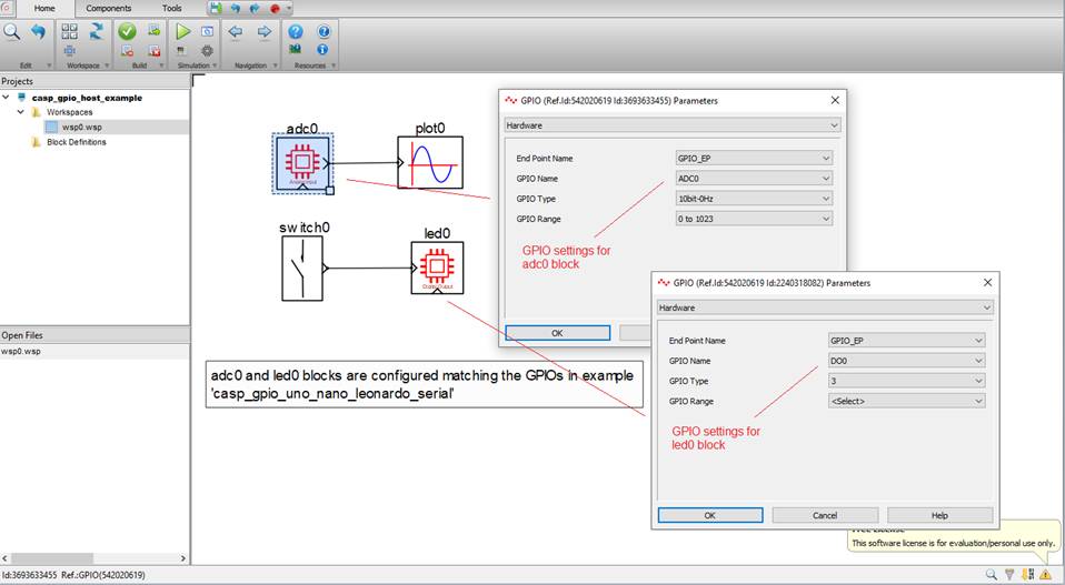
Step 3: User can now use the GPIO blocks on the host CASP model that was configured in above step to directly access these pins. The example project ‘casp_gpio_examples/arduino_boards/casp_gpio_host_example’ shows how to acquire ADC data and control on-board LED on Arduino Uno using CASP GPIO. Screen shot of the model is shown below.
Step 4: User can also access these GPIO pins on the host using Python. This is further elaborated in this section.