

To use
connected hardware IOs in CASP model, the connected hardware end point input
output (EPIO) model has to be imported into CASP. The required user interface
to import EPIO model can be accessed from Home->Simulation->Configure
Simulation IO menu item or by pressing ![]() icon in main
tool bar.
icon in main
tool bar.
Dialog Box and Parameters
Communication Status Window

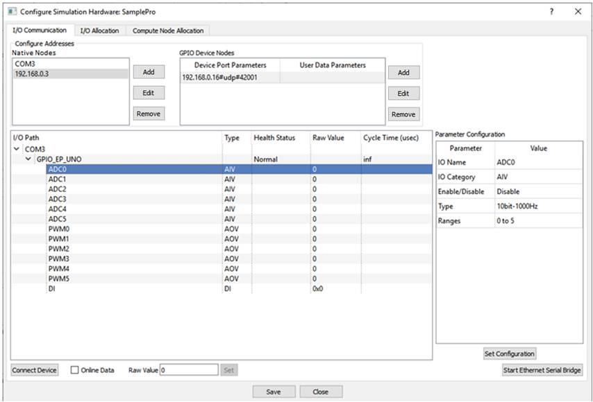
· I/O Communication Tab
|
Native Nodes |
Add |
Add new communication channel such as serial port, local IP address etc. at native hardware end. On pressing Add button a dialog box appears to select protocol and serial port / IP address present on native hardware. Select the options as required. ‘Resultant Tag’ is generated based on the user selected options. ‘Resultant Tag’ field is editable by the user and is used further by CASP. |
|
Edit |
Edit selected node. User interface is same as Add button. |
|
|
Remove |
Remove selected node |
|
|
GPIO Device Nodes & User Data Parameters |
Add |
Add connected device side parameters such as protocol, serial baud rate, IP/MAC address, IP port, client/server etc. On pressing Add button a dialog box appears to select these parameters. ‘Resultant Tag0’ is generated based on the user selected options. ‘Resultant Tag0’ field is editable by the user and is used further by CASP. User Data Parameter is required when the connected device is configured with CASP_UDIO data type. CASP_UDIO data type consists of User Data Input (UDI) and User Data Output (UDO) end point IO categories described in Parameter Configuration section below. User data parameters can be configured along with the GPIO Device Node parameters in the above dialog box. User data parameters typically consist of End Point name and send & receive data sizes. ‘Resultant Tag1’ is generated based on the user selected options. ‘Resultant Tag1’ field is editable by the user and is used further by CASP. |
|
Edit |
Edit selected item from list. User interface is same as Add button. |
|
|
Remove |
Remove selected item from list. |
|
|
Communication Status Window |
- |
This window indicates status of communication parameters such as connected devices, end point names, end point IO names etc. |
|
I/O Path |
Displays connected device path tree |
|
|
Type |
Displays IO type |
|
|
Health Status |
Connection status of connected device |
|
|
Raw Value |
Display raw during device communication |
|
|
Cycle Time (usec) |
Display cycle time or device response time during device communication |
|
|
Parameter Configuration |
- |
Allows user to configure some parameters related to device parameters during device communication test run. |
|
IO Name |
Displays selected End Point IO Name |
|
|
IO Category |
Displays selected End Point IO Category. Available IO categories are as under: DI: Digital Input DO: Digital Output AII: Analogue Input Current AIV: Analogue Input Voltage AOI: Analogue Output Current AOV: Analogue Output Voltage PC: Pulse Counter UDI: User Data Input UDO: User Data Output |
|
|
Enable/Disable |
Enable/Disable EPIO outputs (for DO, AOI, AOV, UDO) during test run. |
|
|
Type |
Indicates data type depending on EPIO category. |
|
|
Range |
Indicates field value range of EPIO |
|
|
Set Configuration |
Uploads parameter configuration to device memory. |
|
|
Connect Device |
- |
Establishes communication with connected hardware. |
|
Online Data |
- |
This check box starts communication with connected hardware device and displays online data in communication status window. |
|
Raw Value |
- |
Displays raw value of selected EPIO during device communication |
|
Set |
Sets raw data for selected EPIO. Applicable only for DO, AOI, AOV and UDO IO categories. User has to first enable these IO from Parameter Configuration before setting the values online. |
|
|
Save |
- |
After importing and validating the hardware through ‘Online Data’ discussed above. The EPIO model can be saved by pressing Save button. The saved EPIO model can be accessed later in project model through GPIO block. |
· I/O Allocation Tab
Displays allocated GPIO blocks in a tabular form.
· Compute Node Allocation Tab
This is under development.