

Model:
Model is a set of interconnected blocks that represents a problem or task. User creates a model to define a certain problem or to check a block’s behaviour. Model is then build and simulated/executed on selected target.
Block:
Block is a basic entity that defines a pre-defined task and is graphically displayed as a square box with ports. Blocks are divided into primary and secondary blocks.
· Primary Blocks are represented by a sub-routine and cannot be further divided in to sub-blocks.
· Secondary Blocks are represented by a group of primary blocks.
Behaviour of the block in a model can be altered by configuring the block parameters. Refer here for further information on blocks.
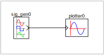
Model Block
Port Block Connecting
Wire![]()
![]()
![]()
![]()
Block Port:
Each block port represents an interface for connecting to other block ports. Block ports are divided primarily based on direction of data flow as below
· Output Port: Represents data source to connected input ports. Output ports are graphically shown with ‘>’ symbol directing outwards to the block.
· Input Port: Represents data sink to connected output port. Input ports are graphically shown with ‘>’ symbol directing inwards to the block.
· Physical Port: Represents an energy conservation port of physical element contained by the block. Physical ports are graphically shown with ‘-‘ symbol.
Connecting Wires:
Connecting wires connect two ports of same or different blocks. Connecting wires are represented by a line. Following rules apply for connecting two ports:
· Two output ports cannot be connected to each other.
· One output port can be connected to more than one input port.
· Physical port can only be connected to other physical ports and cannot be connected to input or output ports.
· Port data type and size shall match for connecting two ports.