Desktop computers, laptops and SBCs generally do not have GPIO pins to interact with outside world. For example if a user needs to plot temperate data on a computer, first they have to program a suitable micro-controller board to read the value from ADC pin connected to a temperature sensor. Then the value that was read has to be transferred to the host computer before plotting it. All these steps require user to know about micro-controller programming, communication aspects and off-course suitable program to plot the values.
‘CASP Remote GPIO Pins’ (RGPIO) feature allow user to view a connected micro-controller’s GPIO pins as if they were part of the host computer. The micro-controller board GPIO pins are directly accessible from CASP models on host PC. The micro-controller board can be connected to host computer either through USB serial or wirelessly through WiFi communication. CASP supports remote GPIO for most of its supported micro-controller boards.
CASP GPIO support DI, DO, ADC, PWM, DAC and Servo types. DI, DO takes values 0 and 1, while PWM, ADC, DAC have range from 0 to 4095 with Integer32 data type. Servo range is from -90 to +90 with Integer32 data type.
Following steps shall be followed to use this feature.
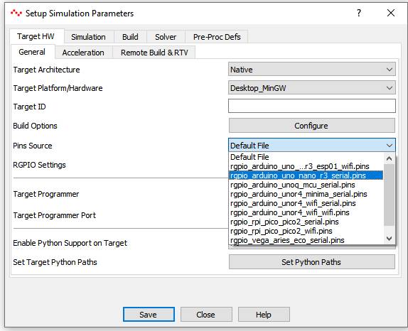
· Connect a supported micro-controller board to the host computer through USB serial. MCU boards supporting RGPIO are listed in Setup Simulation window under ‘Pins Source’ as shown in below figure.
· Program the micro-controller board with binary file located in <casp_installed_directory>/data/rgpio/models folder. For example the binary files for Arduino Uno board are located at ‘<casp_installed_directory>/data/rgpio/models/arduino/casp_rgpio_uno_nano/bin’ folder. Choose a suitable binary file and program the board with CASP Programmer from ‘Tools’ menu. This binary file prepares the MCU to support Remote GPIO pins feature. This step is a onetime activity.
· After the board is successfully programmed, click on ‘Setup Simulation’ and select matching pin definition file from ‘Pins Source’ as shown in below figure.
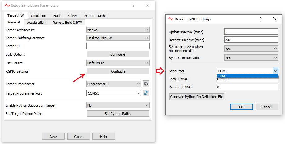
· Now, click on ‘RGPIO Settings’ configure button to set the serial port of the connected MCU board as shown in below figure.
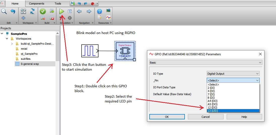
· Things are now ready to use the RGPIO pins in the host model. Just use the pins are normal GPIO pins. For example, below figure shows a LED blink model on host PC