

The required user interface for
setting up simulation parameters can be invoked by pressing Setup Simulation
icon ![]() located under Home->Simulation in main
tool bar.
located under Home->Simulation in main
tool bar.
Dialog Box & Parameters
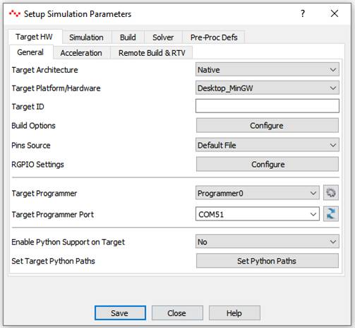
TargetHW - General
|
Target Architecture |
Select target architecture. Select Native for simulating on native hardware. |
|
Target Platform/Hardware |
Select available target hardware from above selected architecture. |
|
Target ID |
Indicates target hardware ID that user has to enter when building for target hardware that supports ‘SimPanel’ such as Android Device and Desktop/Server targets. The hardware ID is indicted in ‘About’ dialog box of SimPanel when executing on target hardware. |
|
Build Options |
Set target hardware specific build options. |
|
Pins Source |
Select target pins source. Typically it could be either ‘UI’ or ‘Default File’. If the target, support remote GPIO then user will be provided with more pin files to choose from. |
|
RGPIO Settings |
Set RGPIO runtime settings. Typically, user should use this option to set RGPIO target board serial port, IP address and port etc. |
|
Target Programmer |
Select target hardware programmer to upload the generated binary file. Default is Programmer0. Programmer1 may be used if target hardware board support package supports it. |
|
Target Programmer Port |
Select or Enter serial port to which target hardware is connected. This option is used to program target hardware. |
|
Enable Python Support on Target |
Enable/Disable python extensions support for the target. Application only for targets that supports Python. This option does not affect CASP command line interface control from Python script. |
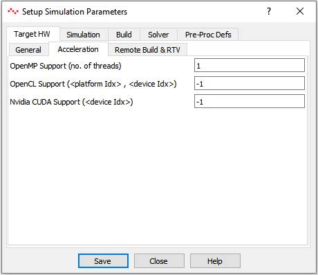
TargetHW - Acceleration
|
OpenMP Support (no. of threads) |
This field globally enables or disables OpenMP support during model execution. 0 – indicates that number of allocated threads is equal to number of logical processing cores available on the target. 1 – indicates only one thread is allocated to OpenMP. Alternately, it indicates OpenMP is disabled. >1: indicates number of logical threads allocated for OpenMP, maximum being number of logical cores available on the target. |
|
OpenCL Support (<platform Idx>, <device Idx>) |
This field globally enables or disables OpenCL support during model execution. It takes two parameters separated by comma. First indicates OpenCL platform index and second indicates OpenCL device index. Value of -1 in platform index indicates OpenCL is disabled. 0 and positive values indicates OpenCL platform and device to be used by blocks having OpenCL code. |
|
Nvidia CUDA Support (<device Idx>) |
This field globally enables or disables Nvidia CUDA support during model execution. Value of -1 indicates CUDA is disabled. >-1 indicates CUDA device index to be used by blocks having CUDA code. |
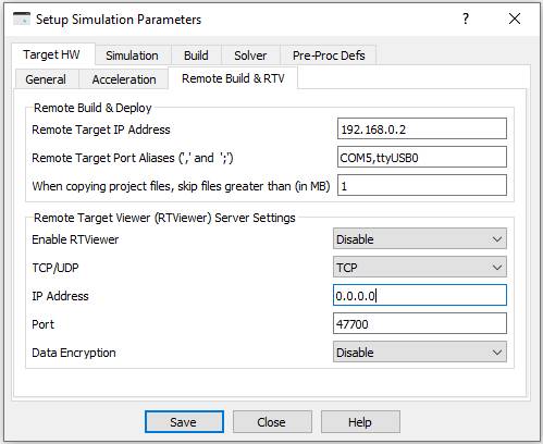
TargetHW – Remote Build & RTV
|
Remote Build & Deploy Options |
|
|
Remote Target IP Address |
Enter IP address of target hardware for remote building. This option is applicable for remote build targets. |
|
Remote Target Port Aliases |
Enter port or IP address mentioned in Compute Nodes of native hardware Simulation IO Panel and corresponding port or IP address on target hardware. The mapping addresses shall be separated by comma. More than one mapping address pair can be entered separated by semi colon. This option is applicable for ‘SimPanel’ targets. |
|
When copying project files, skip the files greater than (in MB) |
Set maximum size of project files to be copied to the target. |
|
Remote Target Viewer (RTViewer) Server Settings |
‘SimPanel’ program embeds CASP remote viewer server feature. This feature allows RTViewer application (configured as client) running on remote computer to connect to this server via a network connection. Below describes various options of the server module running as part of CASP Simulation Panel program. |
|
Enable RTViewer |
Enable or Disable RTViewer server in ‘SimPanel’ |
|
TCP/UDP |
Select either TCP or UDP protocol |
|
IP Address |
Enter IP address of the server. 0.0.0.0 (IPv4) or ::0 (IPv6) indicates the server is listening on all IP addresses available on the computer. |
|
Port |
Enter listening port number between 40000 to 60000. |
|
Data Encryption |
Enable or disable data encryption. |
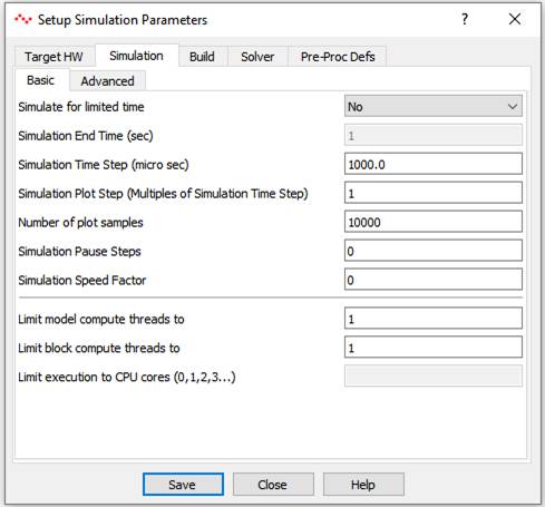
Simulation - Basic
|
Simulate for limited time |
Select Yes or No |
|
Simulation End Time |
Enter simulation end time. Minimum value is 1 sec. Enabled only if limited time simulation is opted in above field. |
|
Simulation Time Step |
Enter simulation time step in micro seconds |
|
Simulation Plot Step |
Enter simulation plot step in multiples of simulation time step. |
|
Number of plot samples |
Enter number of plot samples for plotter. Typical range is between 1000 to 10000. |
|
Simulation Pause Steps |
Indicates number of simulation time steps after which simulation shall be paused. |
|
Simulation Speed Factor |
Indicates simulation speed. 0 indicates full speed with no wait states inserted. 1 indicates real time. Between 0 and 1: slower than real time Above 1: Faster than real time Valid range for target hardware: 0 or 1 |
|
Limit model compute threads to |
This option enable user to limit the available CPU cores for simulation. i.e. Two or more blocks can be executed in parallel. Setting 0 uses all available CPU cores for model execution. Default value is 1. |
|
Limit block compute threads to |
This option enables each block to spawn more than one thread for executing its code if required. Setting 0 makes all CPU cores available for each block. Default value is 1. |
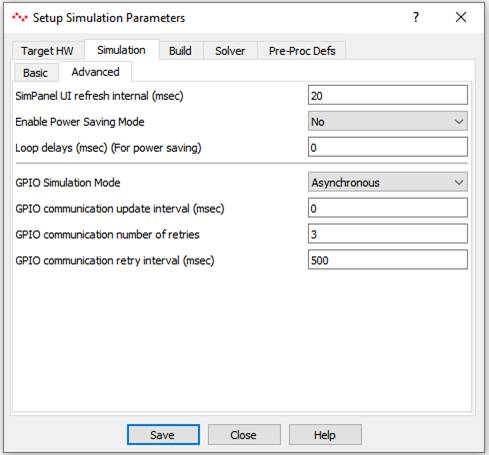
Simulation – Advanced
|
SimPanel UI refresh interval (msec) |
Enter simulation panel user interface refresh interval in msec. Use lower values for faster refresh intervals and use higher values to save power. |
|
Enable Power Saving Mode |
This option tries to save power consumption during simulation. |
|
Loop delays (msec) |
Enter loop delay time that is introduced in main and worker thread loops. A non-zero value will reduce power consumption while increasing the simulation time. This option can be used in situations where power consumption is of primary importance than performance. |
|
GPIO Simulation Mode |
This option tells GPIO blocks during simulation on native hardware when to communicate with external connected hardware. Asynchronous: Communication to external hardware is not synchronized with simulation time step. Sync. Time Step: Communication to external hardware is synchronized with simulation time step. Sync. Plot Step: Communication to external hardware is synchronized with simulation plot step. (Default option) |
|
GPIO Communication update interval (msec) |
Enter GPIO communication update (send + receive) interval in msec. Choose higher values to save power. |
|
GPIO Communication number of retries |
Enter number of retries during GPIO communication. |
|
GPIO Communication retry interval (msec) |
Adjust retry interval when communicating with connected GPIO hardware via Serial or Ethernet communication. |
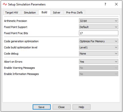
Build
|
Arithmetic Precision |
32bit, 48bit, 64bit. 48bit is only applicable for FPGAs. |
|
Fixed Point Support |
Enable fixed point support. Default indicates that it depends on target configuration. |
|
Fixed Point Fraction Bits |
Applicable for target hardware supporting only fixed point math. |
|
Code generation optimization |
Select optimize for memory or speed. |
|
Code build optimization level |
Inline with GCC compiler tool chain optimization levels |
|
Code debug |
Select debug options for target hardware. This option generates SIM_DEBUG_LOCAL and/or SIM_DEBUG_REMOTE pre-processor definitions based on the selection. User can use this pre-processor definition for writing debug code. |
|
Abort on Errors |
If Yes then build process is aborted if errors are present |
|
Enable Warning Messages |
Select Yes to display warning messages during compilation |
|
Enable Information Messages |
Select Yes to display information messages during compilation |
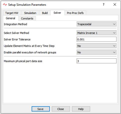
Solver - General
|
Integration Method |
Choose suitable integration method for solver |
|
Select Solver Method |
Select among available methods for matrix inversion based on target hardware capabilities. |
|
Solver Error Tolerance |
Enter error tolerance if iterative solvers are selected for matrix inversion. |
|
Update Element Matrix at Every Time Step |
Applicable if nodal network is having non-linear elements. If No is selected then element matrix is updated (and inverted) only if any element value is changed. |
|
Enable parallel execution of network groups |
Enables parallel execution of network groups if more than network group is present. |
|
Maximum physical port data size |
Useful during solving multi-phase electrical networks. |
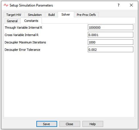
Solver - Constants
|
Through Variable Internal R |
Indicates default internal R (i.e. cross by through) variable that shall be assigned to a through variable. This option Is applicable for physical port blocks having through variable. |
|
Cross Variable Internal R |
Indicates default internal R (i.e. cross by through) variable that shall be assigned to a cross variable. This option Is applicable for physical port blocks having cross variable. |
|
Decoupler Maximum Iterations |
Enter Decoupler block maximum iterations. |
|
Decoupler Error Tolerance |
Enter Decoupler block error tolerance. |
Pre_Proc Defs
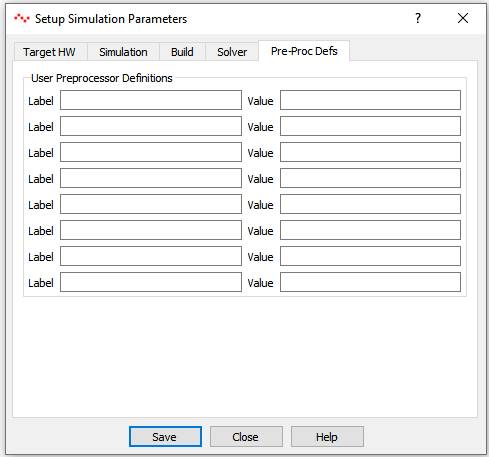
|
Label-Value Pair |
User can add pre-processor definitions in these fields. These are reflected in global header file as - #define <label> <value> pair |